Computational Fluid Dynamics (CFD) in the Cloud
Engineers designing HVAC systems face the challenge of meeting aggressive sustainability and energy-efficiency targets while delivering comfortable environments at a reasonable cost. Traditional design methods involve the use of hand calculations requiring many simplifying assumptions, which limit the calculations’ accuracy. Increasingly, engineers are moving to computational fluid dynamics (CFD), which enables them to compute airflow patterns and space temperatures based on complete 3D geometries with far fewer assumptions and, thus, much greater accuracy.
Factors limiting the use of CFD have been lengthy modeling and setup time, expensive software licenses, and extensive training requirements. These challenges are being overcome with a new generation of cloud-based software enabling engineers to access leading-edge CFD capabilities from the cloud on an as-needed basis in a fraction of the time and cost involved in using conventional CFD tools. This article will explore how cloud-based CFD software can be used to optimize several different types of HVAC systems.
Ensuring Thermal Comfort With Engineering Simulation
CFD streamlines the task of designing HVAC systems that deliver thermal comfort by providing accurate predictions of the performance of any design iteration in minimal time.
For example, CFD was used to evaluate thermal comfort in a living space (Figure 1). The first step involved uploading the computer-aided design (CAD) model of the space. (Another option was to connect directly to a model created with cloud-based CAD software.) The next step was to divide the area of interest—in this case, the air inside the space—into many small finite-volume cells to create a computational mesh. (Typically, engineers vary the level of detail in a model by applying a higher density of cells in areas in which high transients are expected, such as in the area of physical walls and heat sources.) The next step was to set up the physics, which, as is typical, were simple because the flow was slow and possessed a low Reynolds number.
In the simple example shown in Figure 1, the user assigned a fixed value of temperature to the radiator and walls and selected natural convective heat transfer and a K-omega turbulence model. Additional physics options were selected from a template providing only the options for this type of problem. Then, the user pressed the “Start” button to begin the computation on a high-performance-computing cluster in the cloud. The results included velocities, pressures, and temperatures throughout the computational domain. The results were the same as with conventional CFD; what was different was they were obtained with a few simple commands on a Web browser by following a series of prompts.
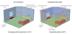
This example shows how easy it is to change design parameters to better understand impacts on thermal comfort. CFD simulations of design iterations were performed to achieve the optimal temperature distribution in the space for a given set of parameters. Figure 2 shows the effect of insulated side walls on average temperature in the space. In this case, an average room-temperature rise of 3°C, or 18 percent, was achieved with insulated side walls, providing better thermal comfort for the same inlet air temperature.
Passive vs. Active Ventilation: Impact on Energy Efficiency
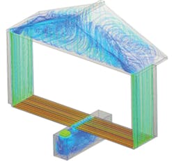
With active ventilation systems—forced-air heating and cooling, heat pumps, radiant panels, chilled beams, etc.—purchased energy is used to provide comfort. With passive ventilation systems, ambient energy sources such as natural airflow, wind, and indoor-outdoor temperature differences are used to draw and circulate fresh air. Passive ventilation can increase energy efficiency substantially by eliminating or drastically reducing the use of purchased energy. IBEEE, a holistic development and engineering service based in Klangenfurt, Austria, used browser-based CFD to compare and contrast the performance of active and passive heating and cooling systems in the design of a dual outer wall (Figure 3).
IBEEE’s design was engineered so convective flow in the air hull surrounding the building provides cooling during the summer and heating during the winter. Stack effect is used to control temperature and air distribution, eliminating the need for fans. As part of the engineering process, two simulations were carried out. The designs were identical, except for the fact one used an active HVAC system and the other used a passive system. The simulation showed a 40-percent-higher flow rate with the passive system than with the active system.
Contamination Control in Cleanrooms With CFD Analysis
Cleanrooms represent a special case of HVAC design in which the goal often is to quickly remove as much contamination as possible. Engineers guided by CFD can achieve this and other design objectives faster because CFD enables them to visualize airflow patterns and analyze particle-migration paths for any proposed design. Figure 4 shows the analysis of three designs and their comparison with SimScale simulation software in a study of interior flow-recirculation regions and the spread of contaminants. Pressure was designed to be slightly below ambient to ensure contaminants did not leak out of the cleanroom. The base design had three central inlets on the ceiling and outlets along the floor, while the second design had nine distributed inlets on the ceiling and side-vent outlets along the floor, and the third design had nine distributed inlets on the ceiling and a raised-floor distributed-outlet design. For each design, the total inlet flow rate was the same; therefore, the energy requirement remained unchanged.
The simulation results in Figure 5 show a large recirculation area in the upper side regions of the first design, which enabled contaminants to spread through the recirculation area. The second design showed small recirculation areas in the side and middle regions. Contaminants were exhausted out of the side outlets; however, contamination control in this case depended on contaminants being released near the side vents. The third design provided the best performance, with only a few small recirculation areas at the side top corners, resulting in good contaminant control, regardless of the position from which the contaminant was released. The recirculation area of Design 3 was approximately 35-percent less than that of Design 1, resulting in faster and more complete clearing of contaminants.
Conclusion
CFD tools in the cloud can reduce the time and cost required to achieve thermal comfort, minimize energy consumption, and clear contaminants by providing insights, such as predictions of comfort with different design alternatives and quick evaluations of different “what-if” scenarios, early in the design process.
The result is users can optimize HVAC designs in less time and at lower costs than was possible in the past. It should come as no surprise, then, that an Aberdeen Group research study1 found design engineers for best-in-class companies are 15 percent more likely than the industry average to use CFD to make design trade-off decisions.
Resources
- Boucher, M. (2011). Optimizing product development time by using cfd as a design tool. Available at http://www.solidworks.com/sw/docs/0308-7117-RB-CFD-012-simulation.pdf
Jerry Fireman has been writing about HVAC and other applications of computational fluid dynamics for more than 20 years.
Did you find this article useful? Send comments and suggestions to Executive Editor Scott Arnold at [email protected].


