Rightsizing UV-C Lamps for HVAC Applications
Over time, organic material can accumulate on HVAC cooling coils, reducing heat-transfer effectiveness.1 Often, system controls and building engineers compensate by increasing fan speed, lowering chilled-water temperature, and even pumping more refrigerant, all at the expense of energy efficiency. Ultraviolet-C (UV-C) energy can be used to irradiate HVAC cooling coils, returning resistance to airflow and heat-transfer efficiency to as-built levels and allowing building engineers to slow fans, add variable-frequency drives, configure chillers to original design parameters, and more. Energy savings of 10 to 30 percent have been reported once coil capacity is restored.
Traditionally, sizing UV-C lamps for the purpose of irradiating HVAC cooling coils depended on trial and error and rules of thumb. That changed with the publication of the 2011 edition of ASHRAE Handbook—HVAC Applications,2 Chapter 60 of which provides a quantitative approach to lamp sizing resulting in systems meeting performance requirements at the lowest initial and long-term operating costs. This article summarizes that guidance and offers a method to simplify future designs.
Calculating UV-C Energy
Specifying UV-C energy can be likened to lighting a small room in which distribution of light is paramount. For example, for a conference room, lighting engineers use an industry reference for a specific amount of light (lumens per square foot) striking the conference table. A common lamp for such a room is a linear 4-ft fluorescent tube. Given that, a lighting engineer can use the 4-ft fixture’s lumens-per-watt baseline and size the number of fixtures, in watts, accordingly. Similarly, ASHRAE provides recommendations in UV-C terminology: microwatts per square centimeter (µW/cm2) striking a coil surface. (Lamp watts will be discussed later.)
ASHRAE’s microwatts-per-square-centimeter levels are based on vast amounts of application data showing UV-C doses are cumulative. For example, the number of seconds in a 30-day month is 2,592,000 (60 sec × 60 min × 24 hr × 30 days), meaning one microwatt will deliver nearly 2.6 million microwatt-seconds of cumulative UV-C energy in a 30-day month. The coil-cleaning effect of UV-C energy accelerates over time, as cleaner coil surfaces increase the reflectivity of the UV-C waveform, making it more efficient within a coil’s interior.
According to Chapter 60, the use of reflectors can reduce the number of lamps required for coil irradiation; however, it also reduces airborne-infectious-microbe kill ratios. It is not surprising, then, that ASHRAE’s recommendations for coil irradiation are such that the more expensive fixturing, custom lamps, and unusual plenum layouts associated with reflected lamp energy are not required. Those sizing UV-C installations are thought to be better served by keeping kill ratios as high as possible.3
Ensuring Effective Irradiation Levels
UV-C-lamp manufacturers publish microwatts-per-lamp-watt (µW/W) data. Measurements are taken 1 m from a lamp’s surface. In plenums, however, lamps typically are installed 12 in. from coil surfaces. Because UV-C light follows the inverse-square law (intensity = 1 ÷ distance2), the closer a lamp is to a coil, the greater the amount of energy striking the coil.
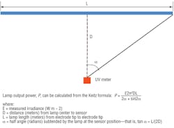
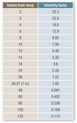
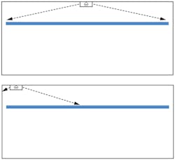
UV-C lamps range linearly in size to 48 in. They are diffuse-area sources, not source points (i.e., flashlights), so intensity and view factors that better represent the energy received by a surface have been developed. Based on work by Keitz4 (Figure 1), the factors in Table 1 have been used successfully. Table 1 and view-factor modeling (Figure 2) enable designers to convert lamp manufacturers’ watt and/or microwatt output data to doses received at various distances to arrive at irradiance contours in microwatt values at different points.
The average UV-C-lamp length is close to 36 in. According to an average of published manufacturer data, a 36-in. high-output (HO) lamp is rated at 80 W and puts out 245 microwatts of UV-C-light-wave energy per square centimeter (µW/cm2) at 1 m, based on radiometric readings. Using the intensity-factor chart (Table 1), we find that at 12 in., the intensity would be 1,588 µW/cm2 (245 × 6.48). Using the more accurate cylindrical view-factor model,5 a surface would see 1,375 µW/cm2 from the same lamp. Both results exceed the Handbook’s recommendation.
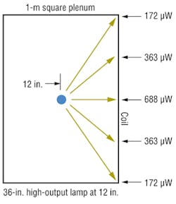
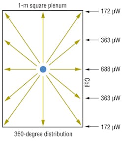
As shown in Figure 2, the greatest amount of a linear lamp’s energy strikes the centermost part of a coil directly across from the middle of the lamp, while the least amount of energy strikes at the ends of the coil. When a single lamp will be positioned at a coil, the irradiance (Figure 3) can be determined via view-factor modeling.5A designer needs to ensure the Handbook recommendation of 100 µW/cm2 at the ends and corners of the coil is met. This entails looking at the environment in which the lamp will operate, focusing on temperature, air velocity, and reflectance.
The first factor to examine is temperature. Derating a lamp’s output is required because lamps most commonly are located downstream of a cooling coil in an air-conditioning system. Taking the maximum output derating of 50 percent for a 500-fpm, 55°F air stream, we have 794 µW/cm2 (1,588 ÷ 2) at 12 in. from the intensity-factor chart and 688 µW/cm2 (1,375 ÷ 2) from the more conservative view-factor model with which to work. We will use the view factor from here.
The next factor to determine is the minimum amount of energy at the coil corners (the farthest points). For a 1-m square surface, the view factor predicts this value to be 25 percent of the highest value, or 172 µW/cm2 (688 × 0.25) (Figure 2).
Now that output has been derated, it is important to consider that most systems typically operate in cooling mode for only a portion of a day and part of a year. At other times, temperatures are higher, which yields higher kill ratios. This could be important during winter.3
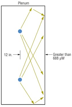
The next consideration is reflectance, or the amount of UV-C energy that bounces off the top, bottom, and sides of a plenum toward a coil, etc. (Figure 4). If a plenum is constructed of galvanized steel, at least 50 percent of the UV-C energy striking its surface will be reflected as a single bounce value, although as many as seven bounces are found in the view-factor model. Using a single bounce provides at least an additional 86 µW/cm2 (172 × 0.50), which can be added to the 172 number for a total of 258 µW/cm2 at the farthest point, which fills in the contour to well above recommendations. Surfaces such as stainless steel and aluminum provide up to 40-percent and 75-percent reflectance, respectively. Providing additional reflectance increases the amount of energy striking a coil and introduces more energy to the air stream to kill airborne microorganisms. As air circulates through the irradiation field, each “pass” provides an additional reduction (in viability) per unit volume of microbes.3
Lamp manufacturers on ASHRAE’s UV committee agree lamps may differ (slightly) in quality, but not by more than 5 percent in function. When ASHRAE’s recommendations are met, the acquired data can be used to simplify future designs. For example, an 80-W, 36-in. HO lamp was found to work successfully on a coil that was 1-m square, or had 10.76 sq ft of surface area. Dividing the lamp wattage by the square footage of coil surface shows that about 7.5 lamp watts per square foot of coil surface area (80 ÷ 10.76 = 7.43) easily met or exceeded recommendations. This becomes a simplified way to properly size future UV installs for most any coil, large or small.
For example, a custom air handler might have a coil 85 in. in height and 120 in. in width, which equates to a surface area of 70.8 sq ft. Multiplying that amount by 7.43 equals 526 W. Sizewise, this coil would be efficiently and affordably served by four 61-in., 145-W HO (360-degree) lamps (580 W total). This works well, with the slight overage adding to a higher fly-by kill ratio. UV-C retrofits are relatively simple to perform. The cost of a properly designed system of 10,000 cfm or more can be 15 cents per cfm or lower, or, often, less than the cost of a properly performed coil-cleaning procedure.
For larger installations requiring multiple rows of lamps, an overlap of light energy (light from lower rows reaches the top of the plenum, while overlap from upper rows reaches the bottom of the plenum) is created (Figure 4). This benefits the sides of the plenum and contributes to the airborne kill ratio.
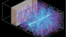
Also worth noting: All parts of a plenum downstream of a cooling coil are subject to the accumulation of contaminants and the formation of condensate, the perfect recipe for microbial growth. With 360-degree UV fixturing (Figure 5), most of the plenum surface will see UV-C energy, both directly and through better overall reflectivity. This keeps the entire plenum clean, reduces the potential for unmanaged microbial carryover to occupied spaces, and reduces maintenance.
Conclusion
Simplifying information enables engineers to write more meaningful specifications and users to more easily convert standard lamp-watt labeling to lamp watts per square foot of coil surface. Additionally, it always is advisable to use nonproprietary components with agency approvals, long warranties, and local sources of replacement materials.
UV-C retrofits are reasonably simple and justifiably affordable. And as long as they are maintained, UV-lamp systems almost always hold the promise of short paybacks, reduced maintenance and employee absenteeism, and sustainable heat transfer with minimal energy use, longer equipment life, and less downtime.
References
1) Fencl, F. (2013, July). Maintaining A/C-system performance with UV-C. HPAC Engineering, pp. 5-6. Available at http://bit.ly/Fencl_0713
2) ASHRAE. (2011). ASHRAE handbook—HVAC applications. Atlanta: ASHRAE.
3) Menzies, D., Popa, J., Hanley, J.A., Rand, T., & Milton, D.K. (2003). Effect of ultraviolet germicidal lights installed in office ventilation systems on workers’ health and well being: Double-blind multiple crossover trial. Lancet, 363, 1785-1792.
4) Lawal, O., et al. (2008, April). Proposed method for measurement of the output of monochromatic (254 nm) low pressure UV lamps. IUVA News, pp. 14-17. Retrieved from http://bit.ly/Lawal_0408
5) Kowalski, W.J., & Bahnfleth, W.P. (2000). Effective UVGI system design through improved modeling. ASHRAE Transactions, 106 (2), 4-15.
The president of UV Resources, Forrest Fencl is the writer or co-writer of 15 patents and the author or co-author of numerous papers and articles and several ASHRAE Handbook chapters related to ultraviolet air and surface treatment. He is an ASHRAE Life Member and Fellow and a member of the International Ultraviolet Association and the Illuminating Engineering Society.
Did you find this article useful? Send comments and suggestions to Executive Editor Scott Arnold at [email protected].
