Every boiler plant has a deaerator that generally gets little or no attention until it “burps,” jeopardizing the entire steam system. These incidents can be expensive to correct and affect the integrity of other critical auxiliary equipment as well as the careers of those charged with technical oversight of utility systems.
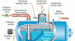
Deaerators are large, insulated tank-car-shaped pressure vessels. They produce preheated boiler feedwater to help ensure efficient steam-plant operation. Deaerators come in numerous sizes and shapes, depending on boiler-plant design, capacity, and system pressure rating. The units are produced in spray (Figure 1), tray, spray-tray, vacuum, and atmospheric pressure designs.
Benefits
Deaerators provide many benefits to a steam-plant system, including:
- Serving as a surge collection tank for process condensate return.
- Blending hot return condensate and cold makeup water.
- Preheating feedwater uniformly to improve boiler efficiency.
- Removing oxygen (O2) and carbon dioxide (CO2) from feedwater to mitigate corrosion.
- Holding 13 to 15 min of treated hot water in reserve storage for load change.
- Providing a location for feeding and blending chemicals and testing protocol.
- Providing a constant, pressurized supply of water to boiler feed pumps.
- Providing a convenient location for instrument controls and feedwater test data.
- Helping to ensure precise drum water level and pressure inside of a boiler.
Most deaerators are American Society of Mechanical Engineers- (ASME-) certified pressure vessels that operate at 5 to 15 psig by utilizing a low-pressure steam supply. A safety valve must be installed to ASME International Boiler and Pressure Vessel Code requirements. Quality pressure and temperature sensors are essential to ensuring precise pressure control and achieving a water temperature of 225°F (the minimum temperature required to remove dissolved O2 and CO2 from feedwater) in the deaerator's storage section through mechanical evaporative scrubbing.
At this elevated temperature, feedwater pumps, piping, and economizers are subject to severe O2 corrosion attacks even though only a minute level of O2 is dissolved in the water. When properly operating, a deaerator should be able to scrub O2 to 5 to 10 ppb residual.
Typically, a ½-in. vent pipe in a deaerator's stainless-steel-dome degassing chamber removes noncondensable gases. A steam plume of 18 to 24 in. should be visible at the end of the vent pipe.
The addition of sulfite or hydrazine chemically ensures a “zero” level of dissolved gas in the feedwater. (The chemical-reaction equation is: 2 Na2SO3 + O2 = 2 Na2SO4, which represents a soluble salt removed in blowdown.) A ¼-in. stainless-steel pipe should be used to distribute the liquid sulfite or hydrazine inside the deaerator storage section about 6 to 12 in. below the normal water level (NOWL). Daily testing of boiler blowdown water should confirm a sulfite residual of 25 to 40 ppm, ensuring zero O2 residual in the feedwater system (Figure 2).
Structural Integrity
During the 1950s and ‘60s, several deaerator manufacturers fabricated units with medium carbon steel, keeping vessel metal thickness below ½ in. and eliminating the need to stress-relieve the welds. Numerous units developed weld cracks because of cyclic thermal and circumferential stresses, and several experienced catastrophic failure. Since then, many units have undergone weld repair, stress relieving, and recertification. Most insurance carriers now require a thorough nondestructive inspection of all welds every five years. This condition is somewhat different from vessel internal corrosion, which is caused by ineffective water treatment or deaerator performance.
When properly installed and controlled, deaerators are designed to provide continuous boiler operation, incurring significant load changes without operator involvement. Variability in pressure, temperature, or water level in a deaerator can cause water hammer, auxiliary-equipment malfunction, and boiler operational anomalies. Therefore, deaerators generally are well-instrumented. As such, the instrumentation data available not only can provide system reliability, but critical information for a boiler-system critique.
A deaerator chemical balance can determine the percent of condensate return from the process systems required for a boiler-system technical analysis. Generally, commercial and industrial plants should achieve a minimum of 75- to 80-percent condensate return unless steam or condensate is used for direct injection in the process (Figure 3).
A deaerator energy balance then can be developed to determine deaerator steam usage and other energy data needed for a critique of the entire steam system (Figure 4). After establishing condensate return and deaerator steam usage per thousand pounds of steam produced, an overall energy balance of the boiler can be developed. Knowing energy values, such as fuel energy per unit of steam production, pound of fuel per pound of steam, or British thermal units of fuel per British thermal units of steam, adds to a critique of overall steam-plant operation (Figure 5).
Operational Checklist
A checklist can be used to evaluate the operational integrity of a deaerator unit. Checklist items should include:
- Storage-section volume for 13 min of water (from NOWL to pump low-level trip).
- A normal pressure of 5 psig, ensuring a minimum temperature of 225°F.
- Readily accessible utility-grade pressure and temperature gauges and/or sensors.
- A ½-in. vent gas-purge pipe with a plume of 18 to 24 in.
- A stainless-steel sulfite chemical feed line inside the vessel storage section.
- A sulfite line (quill) located 6 to 12 in. below the NOWL.
- An evaluation of daily sulfite use. (A large change can indicate a spray-valve or tray-box malfunction.)
- Semi-annual testing of unit performance/dissolved O2 without chemical feed.
- Quality liquid-level gauge glass easily visible by operators to monitor and confirm water level.
- A well-insulated tank, including valves and man-heads.
- An unrestricted discharge pipe to ensure adequate net positive suction head available for feed pumps.
- An annual internal inspection for debris, corrosion, or defective components.
- Annual planned maintenance and calibration of all instruments.
- Nondestructive tests of all vessel welds on a five-year basis.
Conclusion
A deaerator is not only an essential auxiliary component of a reliable feedwater system, but the heart of a boiler mass-flow and thermal-energy database that can be used to critique plant operations and identify energy-savings opportunities. For facilities that have boiler-efficiency discrepancies (generally fuel- and steam-meter inaccuracy and/or rudimentary combustion controls), the equations in Figure 5 can be used to identify these issues.
Whether a deaerator is for a large 80,000-pph watertube boiler system or a small 300-hp firetube unit, significant energy savings may be possible in plants that do not monitor feedwater-system performance closely. If boiler efficiency is not at its peak (and the cause of the inefficiency cannot be identified), a critique of the feedwater system may be revealing.
Many facilities use steam and fuel meters to determine boiler efficiency. Frequently, these meters are not accurate and utilities staff members may have a false sense of boiler efficiency. If a facility spends more than $50,000 per month on boiler fuel, a 5- or even 10-percent efficiency improvement may be possible.
An unscheduled deaerator outage can be a serious issue, affecting process operations, energy costs, maintenance budgets, and the long-term integrity of the entire boiler system. Get to know and respect this unit as a boiler plant's major auxiliary system.
President of JoGar Energy Services and a member of HPAC Engineering's Editorial Advisory Board, Gary Wamsley, PE, CEM, is a mechanical engineer with 40 years of technical management and operational experience in plant and staff engineering. He has developed and presents training programs on the energy optimization of boiler operations, water and steam treatment, industrial energy management, and combustion, compressed-air, centrifugal-pump, and thermal-process systems. He can be contacted at [email protected].
