Like all materials, pipe experiences dimensional changes as a result of changes in temperature, expanding when heated and contracting when cooled. The key to accommodating thermal expansion and contraction in a piping system is to allow predictable and controlled piping-system movement.
Inadequate movement accommodation can cause excess stress on a piping system, resulting in ruptures and leaks; increased stress on boilers, chillers, valves, and other equipment/components; and escalating downtime and labor expenses. This can impact building owners negatively, increasing maintenance costs and the likelihood of business shutdowns.
This article discusses four methods of allowing flexible, controlled piping-system movement provided by grooved mechanical pipe-joining systems.
THERMAL MOVEMENT
When a piping system is subjected to varying temperatures, it may experience horizontal movement, vertical movement, and angular deflection simultaneously. Vertical and horizontal piping systems can experience additional strains. For example, space constraints can be a major obstacle around a horizontal piping system's length and turns. Vertical-piping considerations should involve dynamic, static, and elevation-head calculations of the pressures and loads exerted on the lower portion of the system.
Carbon-steel pipe experiences thermal expansion or contraction at a rate of 0.75 in. for every 100°F change in temperature per 100 ft of pipe. The piping typically is placed in stressful conditions, under which reactive forces can damage components or equipment. The forces generated are often significant; movement must be accommodated and controlled to prevent transmission of stresses throughout the piping system.
GROOVED MECHANICAL PIPE-JOINING SYSTEMS
A grooved mechanical system can accommodate thermal pipe movement in four ways:
-
By utilizing the linear movement/deflection capabilities of flexible grooved couplings.
-
By providing an expansion joint that utilizes grooved-mechanical-pipe components.
-
By providing an expansion loop that utilizes grooved-mechanical-pipe components.
-
By allowing a piping system to “free-float.”
Flexible grooved couplings for linear movement and deflection
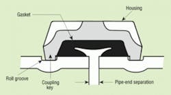
The design of a grooved mechanical coupling's components permit pipe movement (Figure 1). The coupling key's dimensions are narrower than the groove in the pipe, allowing the coupling key to move in the pipe groove. Additionally, the coupling housing's width allows the pipe end to separate, leaving room for controlled linear and angular movement. The mechanical coupling remains a self-restrained joint, and its pressure-responsive design provides sealing even under deflection and pipe movement.
Grooved mechanical couplings are an alternative to welded U-shaped expansion loops, welded offsets, expansion joints, and rubber bellows. The couplings accommodate movement within a piping system's “free range of motion,” meaning piping-system movement caused by thermal expansion and contraction can be accommodated in smaller spaces with little stress on components.
Grooved mechanical couplings are either “rigid” or “flexible.” Rigid grooved mechanical couplings “fix” a joint in its installed position and do not permit linear, angular, or rotational movement at the joints. Flexible grooved mechanical couplings permit controlled linear and angular movement capable of accommodating pipeline deflection.
Used at changes in direction and directing pipe movement toward directional changes with anchors and guides, flexible couplings accommodate movement themselves. This technique produces little or no additional stress on a piping system.
Flexible couplings can be used strictly for their axial-movement capabilities. In this case, straight runs are anchored on each end, and piping is guided at every other pipe length. Each flexible joint is pre-gapped (either fully gapped or fully closed/butted) at installation to ensure there are enough couplings to accommodate the expected expansion/contraction.
Flexible grooved couplings allow angular flexibility and rotational movement to take place at joints (Figure 2). To determine the appropriate number of couplings to use, compute the change in the linear length of a piping system by considering the length and size of the piping system as well as the maximum and minimum operating temperatures.
When full linear movement is required, a grooved expansion joint can be used. It should be noted that fully deflected joints cannot provide linear movement. However, partially deflected joints can provide some portion of linear movement. It is important to consider that standard cut-grooved pipe can provide double the expansion, contraction, and deflection capabilities of same-sized standard roll-grooved pipe.
Offsets that utilize grooved mechanical joints must be capable of deflecting enough to prevent harmful bending (Figure 3). If pipes expand because of thermal changes, further growth can be expected at the ends.
Flexible couplings do not automatically provide for piping expansion or contraction. The best setting always should be considered for pipe-end gaps. In anchored systems, gaps must be set to handle combinations of expansion and contraction. In free-floating systems, offsets of sufficient length must be used to accommodate movement without overdeflecting joints.
Ensure anchorage and support is adequate. Anchors should be used to direct movement away from or to protect critical changes in direction, branch connections, and structure. Spacing and types of supports should be considered when accommodating anticipated pipe movements.
Expansion joints with grooved-mechanical-pipe components
Expansion joints can be compressed or expanded axially. A welded expansion joint typically is a rubber- or metal-bellows-type specialty joint flanged into a system and requiring regular maintenance. Other expansion joints utilize grooved mechanical couplings and specially grooved short pipe nipples with flexible couplings placed in long, straight runs of pipe (Figure 4). These types of expansion joints are pre-set to allow the desired amount of contraction/expansion, which can be adjusted by adding or removing couplings. When a series of flexible couplings is installed, the resulting grooved expansion joint can protect equipment by reducing vibration and stress in the system.
Whether using specialty or grooved expansion joints, adjacent piping must be guided properly to ensure movement is directed into the device and no lateral movement is experienced.
To ensure proper performance of specialty expansion joints, a piping system should be divided into separate expansion and contraction sections with suitable supports, guides, and anchors to direct axial pipe movement. Anchors should be classified as “main” or “intermediate” for force analysis.
Main anchors are installed at terminal points, major branch connections, and changes in piping direction. The force acting on a main anchor is caused by pressure thrust, velocity flow, and the friction created by alignment guides and weight-support devices.
Intermediate anchors are installed in long runs, dividing them into smaller expanding sections to facilitate the use of less-complex expansion joints. The force acting on an intermediate anchor is caused by the friction created by guides, the weight of supports or hangers, and the activation force required to compress or expand an expansion joint.
Pipe-alignment guides are essential to ensure axial movement of an expansion joint. If the situation allows, the expansion joint should be adjacent to an anchor within four pipe diameters. The first and second alignment guides on the opposite side of the expansion joint should be located a maximum distance of four and 14 pipe diameters, respectively. Additional intermediate guides may be required throughout the system for pipe alignment. If the expansion joint cannot be located adjacent to an anchor, guides should be installed on both sides of the unit (Figure 5).
Grooved expansion joints may be used as flexible connectors; however, they do not provide simultaneous full expansion and deflection. Expansion joints installed horizontally require independent support to prevent deflection, which reduces the amount of room available for expansion.
Expansion loops with grooved-mechanical-pipe components
In vertical, straight runs of pipe, expansion loops utilizing a U-shaped configuration can be designed to accommodate expansion and contraction. Expansion loops can be welded or grooved. Welded expansion loops require eight welded joints and fittings to assemble. In a welded expansion loop, piping bends or flexes to accommodate straight-run movement. Although this method works, the forces that bend and flex the pipe are much greater than in a grooved loop. Also, the forces generate a larger magnitude of stress requiring larger anchors and guides to direct pipe movement and protect components and structures.
Flexible mechanical joints can be used in expansion loops without inducing stress in pipes, elbows, or joints. It is important to note that expansion loops utilizing rigid couplings are not designed to accommodate angular deflection; however, an expansion loop utilizing rigid grooved copper couplings is designed to conform to industry standards.
Flexible couplings' deflection capability allows thermal expansion/contraction to be absorbed at elbows as thermal forces induce deflection. Eight flexible grooved mechanical couplings, four grooved-end 90-degree elbows, and three pipe spools are required to complete an expansion loop. As system temperatures decrease and the pipe run contracts, the loop expands. The couplings' deflection capability accommodates the movement. As system temperatures increase, the opposite effect occurs as the pipe run expands and the loop contracts. The couplings then accommodate deflection in the opposite direction (Figure 6).
Using flexible couplings in an expansion-loop configuration reduces the amount of force needed to flex the loop. This type of loop will be half to one-third the size of a welded loop with the same capacity. The space constraints of modern buildings make this an attractive HVAC piping option, although welded expansion loops still are required in some system applications.
Free-floating systems
Free-floating piping systems allow thermal expansion and contraction without the use of expansion joints. As long as movement does not cause bending-moment stresses at branch connections, it is not harmful to joints, changes in direction, parts of structures, or other equipment. A free-floating system can be achieved by installing additional grooved mechanical joints or guides to control the direction of movement. Engineers must consider the effects of pressure thrusts when utilizing flexible grooved couplings because a pipe that is allowed to float will move as far as its end gaps permit.
Branch connections and offsets must be long enough so that a coupling's maximum angular deflection is never exceeded and can accommodate the anticipated total movement of a pipe. Otherwise, the system should be anchored and movement directed.
CONCLUSION
Grooved mechanical pipe-joining systems offer four methods of providing flexible, controlled piping-system movement. The selection of flexible couplings, expansion joints, expansion loops, or free-floating systems should be based on the type of piping system and the amount of anticipated movement.
In addition to accommodating thermal expansion and contraction, benefits of the grooved method include a simplified assembly process that is readily inspectable. Also, mechanical couplings reduce the need for welding and reduce man-hours and material handling on site, making job sites safer and reducing the risk of injury. During operation, the simple disassembly of a coupling reduces chances of deferred maintenance and lengthy downtime for routine or unscheduled maintenance. The grooved-mechanical method is an efficient way of accommodating excess stress on a piping system, eliminating ruptures and leaks caused by thermal expansion, decreasing maintenance needs, and simplifying the commissioning process.
Larry Thau is executive vice president and chief technology officer for Victualic Company Inc. A practicing mechanical engineer for more than 35 years, he holds more than 35 patents and lectures on piping technology around the world.
