Replacement of Condenser-Water System in Mixed-Use High-Rise
Replacing or upgrading HVAC systems in older buildings presents a variety of challenges, including difficulty gaining access to mechanical components and limited space for replacement piping. On a recent project involving the replacement of the condenser-water system in one of the tallest buildings in Kansas City, Mo., the mechanical, electrical, and plumbing (MEP) team faced many such challenges. With careful planning and execution, however, the project not only was a success, it resulted in significant cost savings for the owner.
The Building
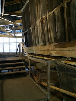
Opened for business in 1986, Town Pavilion is a 38-story mixed-use building in downtown Kansas City. Mechanical floors on the seventh and 36th levels contained chilled-water coils, airside economizers, and fan-powered variable-air-volume boxes with electric heat, while a sub-basement-level chiller plant contained 1985 vintage centrifugal chillers using R-11 refrigerant. Chilled- and condenser-water piping was routed through a vertical interior mechanical pipe chase. Twenty-inch condenser-water supply and return pipes were routed vertically through a mechanical pipe chase from the chiller plant to the 35th-floor mechanical penthouse, where four wood-framed crossflow cooling towers rejected heat to the atmosphere.
A computer-room-air-conditioning (CRAC) water loop provided heat rejection for 11 water-cooled units located at various levels of the building using cooling-tower condenser water. The piping for the CRAC loop had been removed and replaced because of pipe-wall corrosion within the previous five years. Because of the water connection between the CRAC loop and the cooling-tower condenser-water system, the cooling towers had to remain in operation year-round. This required substantial heat to prevent the wooden cooling-tower basins from freezing during winter. When the building was planned and constructed, many more data-center cooling applications were anticipated, but they never were built out.
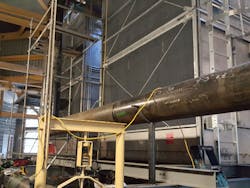
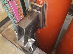
The MEP team used pipe-stress-analysis software to ensure compliance with ASME B31.9, Building Services Piping. Flexible grooved couplings were used for the horizontal routing at levels 6, 7, 33, and 34, while rigid grooved couplings were used for the vertical sections. Spring-support design was delegated to the support supplier. The results of the supplier’s calculations, including pipe movement and stresses, were compared to the MEP team’s original stress analysis and predicted movements. The results of the comparison then were reviewed with the couplings manufacturer to determine the quantity and final locations of the flexible couplings.
Deteriorating Conditions
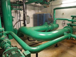
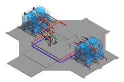
The condenser-water system was showing signs of severe pipe-wall corrosion. Ultrasonic studies revealed piping sidewalls to be as thin as 1/8 in. in some areas, which is considerably less than the 3/8-in. thickness of new 20-in. standard-wall piping. After evaluating several maintenance and repair options, the owner chose to replace the system. The new condenser-water system would include new cooling-tower cells and piping between the chiller plant and cooling towers. A decoupling of the CRAC system would allow the cooling towers to be shut down during winter. The CRAC system would be filled with a propylene-glycol antifreeze solution, operate on dry coolers during winter, and utilize the cooling towers through a plate-and-frame heat exchanger during summer. New CRAC-loop equipment would be added.
Restricted Access
The cooling towers had been installed on the 35th floor at the time of the building’s construction. Removal of the roof for a crane or helicopter lift of materials was not a possibility. All new and demolished components had to be taken to and from the mechanical room via the service elevator. The service elevator’s opening was 4 ft 6 in. wide by 9 ft tall, while the elevator itself was 5 ft 6 in. wide by 9 ft 9 in. tall by 9 ft 4 in. deep. Often, equipment, including dry coolers and cooling-tower supports, had to be sized according to those dimensions.
Cooling-Tower Sizing
The cooling towers were carefully sized and selected to ensure they would work well with the existing chillers, which were nearing the end of their useful life, and new high-efficiency, low-delta-T chillers.
The chiller plant was designed for a 12°F delta-T. It operates at 0.632 kW per ton. The future design is for a delta-T of 10°F or less and operation at 0.23 kW per ton. A number of cooling towers, including the modern version of the existing models, were considered. Ultimately, stainless-steel cooling towers were selected because of their performance and size.
Pipe Demolition/Removal and a Suitable New Chase
Among the owner’s requirements was that no in situ welding occur in the vertical pipe chase and that no cutting torches be used in the removal of the existing system. That the chiller plant could be disconnected from the cooling towers only between Dec. 15 and Feb. 15 severely limited the time frame for working on the condenser-water piping. This, obviously, prevented a direct replacement of the condenser-water system in the same chase, as there was no room to abandon two 20-in. pipes and install two new ones. A search for a new location for a chase began.
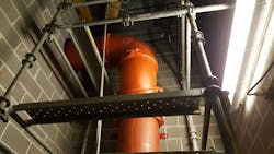
The chase for a mail conveyor system that no longer was used was identified by the owner as a possibility. The MEP team needed to remove the conveyor system from the chase and verify that the new piping could fit within the constraints of the existing floor penetrations and that the existing structural-steel floor framing could support the new pipe loads. Fortunately, the mail conveyor system was almost entirely bolted together, which made removal relatively easy.
The new chase existed only between floors 6 and 34. Some demolition of the existing system and the ability to cross over with a horizontal pipe run was required. Between the chiller plant and seventh level, the existing chase needed to be used. To connect to the new penthouse piping, the pipes needed to jog back to the existing chase on levels 33 and 34 to meet up with the new piping and cooling-tower sump connections. Some of the old piping had to be removed from the existing chase. This was accomplished using non-spark-producing 7 1/4-in. metal-cutting circular blade saws. Once pieces were cut out, they were lowered to the main level of the building and carted away.
The decision to use the vertical mail-conveyor chase instead of removing and replacing materials in the existing chase reduced the project schedule from an estimated four years to less than two years. The reduction in time was attributed to the ability to construct a parallel pipeline in the new vertical chase while leaving the existing pipeline in operation. The only shutdown of the existing system was in the areas above Level 33 and below Level 7, where the pipe was routed in the same location during cold-weather periods, when the chiller plant could be shut down. This saved an estimated $300,000, as the existing pipe could be cut into segments small enough to be carried down the freight elevator and maneuvered around existing corners, a very labor-intensive procedure.
Existing Core Walls
The existing interior core walls of the building had been constructed with substantial steel reinforcement, which, as confirmed by ground-penetrating radar, precluded drilling or cutting through the core walls. This necessitated the routing of pipe around concrete core walls and other piping, a difficult process, and precluded the development of low spots within the piping offsets. Fortunately, the owner was able to allow the use of soffits in utility areas, where the pipe-bottom elevation was below the existing suspended ceiling. The available height above the finished floor was 7 ft 6 in. at the lowest point, which still allowed access to all areas of the building while avoiding the core wall.
Existing-System Energy Usage
The existing system easily was made more energy-efficient by means of decoupling the CRAC-loop system and replacing the cooling towers and CRAC-loop pumps. Decoupling the CRAC loop allowed the removal of the existing electric-basin heat loop, shutdown of the cooling towers during winter, installation of variable-frequency drives on the CRAC-system pumps, and reduction of cooling-tower-fan horsepower. An added feature was the ability to reject heat from the CRAC loop to the cooling-tower basins during spring and fall.
The owner was able to take advantage of an incentive program offered by the local utility company that provided substantial rebates for significant energy reductions.
Power-Requirement Reductions
Every piece of new equipment in the system is lower in nameplate and operating motor horsepower than the equipment it replaced. Cooling-tower-fan motors were reduced from 60 hp to 30 hp each, as the additional data-center spaces for the building never came to fruition. CRAC-loop pumps were reduced from 40 hp to 10 hp by analyzing the existing system and allowing for some future expansion as tenants change. The tower-basin loop heater (180 kW) was removed in its entirety because of the ability to shut down the cooling towers during winter.
From Cooling Towers to Dry Coolers
The CRAC loop required cooling-tower operation, including 60-hp cooling-tower fans and 180 kW of cooling-tower basin heat, year-round. That operating configuration was replaced with two parallel dry coolers that require only four 2-hp fans and one 10-hp CRAC-loop pump. This has resulted in the largest energy savings for the owner and a $358,000 rebate from the local utility.
CRAC-Loop Heat Rejection to Cooling-Tower Basins
Daily temperature changes rapidly in Kansas City during the spring and fall. While daytime operation can require cooling, nighttime temperatures can approach freezing. Therefore, the use of heat from the CRAC loop to warm the cooling-tower basins when needed was suggested. Additional piping and valves were installed so the cooling-tower side of the CRAC-loop heat exchanger dumps heat rejected from the CRAC loop directly into the cooling-tower basins. This requires no use of auxiliary basin heat by the submerged electrical resistance heaters.
Conclusion
The unique challenges of the project led to some innovative solutions and a successful outcome. With the more efficient system, energy costs have been reduced by $48,000 a year, while utility rebates for the new equipment have cut more than 10 percent from the total project cost. System operation has been simplified and maintenance costs related to the cooling towers and associated piping have been reduced. Most importantly, the client is happy.
A senior project engineer for Thornton Tomasetti, Troy Ganson, PE, serves as a property-loss and building-performance consultant. He is well-versed in structural design and building systems, with an extensive background in HVAC and plumbing design. A vice president of Thornton Tomasetti, D. Michael Dowdall, PE, has more than 30 years of experience in mechanical design and forensics, specializing in complex facilities. He also is skilled at commissioning and life-cycle-cost analysis.
About the Author
TROY GANSON
Senior Project Engineer
A senior project engineer for Thornton Tomasetti, Troy Ganson, PE, serves as a property-loss and building-performance consultant. He is well-versed in structural design and building systems, with an extensive background in HVAC and plumbing design.
