Radiant-cooling systems have progressed in the last few decades, garnering attention as a comfortable and energy- and material-efficient option.1 Compared with air systems, radiant-cooling hydronic systems use approximately half the horsepower and materials to move heating and cooling energy within a building. Although radiant-cooling systems have been used in Europe for years, they are starting to be examined — and installed — in the United States.
Low-flow injection-pumping systems can help make radiant-cooling systems even more efficient. Injection-pumping systems deliver heating and cooling energy to a variety of terminal units, including chilled ceiling panels, chilled beams, fan coils, and heat pumps, in the same piping-distribution system, even if each unit requires a different temperature.
THE EUROPEAN EXPERIENCE
Like many hydronic-based-system developments, commercial radiant-cooling HVAC systems originated in Western Europe during the 1980s. Traditionally, European commercial buildings were supplied only with heating systems. With the introduction of personal computers, these buildings began to require sensible cooling.
Europeans then developed radiant chilled ceilings to satisfy the need for indoor cooling. Radiant chilled ceilings consist of metal panels with hydronic tubing attached. Chilled water is circulated through the panels to produce radiant and convective cooling.2 Although many European commercial buildings have limited ceiling space, these systems require only a minimum amount of room because small pipes, rather than large ducts, are used to transport cooling energy. Newer chilled panels use plastic pipes embedded in ceilings, walls, or floors.
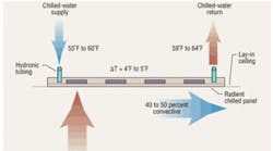
Approximately 50 to 60 percent of the heat transfer from a radiant chilled panel is radiant, while 40 to 50 percent is convective. Chilled-water temperature must be above dew point — between 55°F and 60°F — to prevent condensation from forming on the bottom of the panels. Therefore, the driving force — or temperature difference — between chilled water and a room is reduced to 15°F to 20°F, while a conventional chilled-water system using 40°F to 45°F chilled water reaches temperature differences of 30°F to 35°F.
As a result, higher chilled-water flow rates are required to achieve reasonable capacities. With chilled-water temperature differences or delta-Ts of 4°F to 5°F, flow rates range from 4.5 to 6 gpm per ton. Conventional chilled-water systems have flow rates of 2 to 3 gpm per ton and chilled-water delta-Ts of 8°F to 12°F. Chilled-water flow rates for chilled panels and ceilings are approximately double those of conventional chilled-water systems (Figure 1).
Even with higher flow rates, radiant-chilled panels and ceilings have relatively low capacities, ranging from 20 to 40 Btuh per square foot of panel area. While this is adequate for cooling loads of interior spaces, it may not be adequate for exterior spaces.
Exterior spaces with larger glass areas can approach 60 Btuh per square foot of floor area. For full sensible cooling in exterior spaces, the cooling load must be reduced or the ceiling panels supplemented with other cooling sources. Solar load can be reduced by using window-shading devices, such as interior blinds or exterior sun shades, that close when windows are exposed to direct sunlight. Additional cooling sources include chilled walls or floor panels.3
Because the chilled-water temperature supplied to a radiant chilled ceiling is above dew point, radiant chilled panels cannot provide latent cooling capacity. However, providing a 100-percent dedicated-outside-air system (DOAS) that can accomplish latent cooling allows the combination decoupled system to provide sensible and latent capacity.4
The biggest advantage to decoupling sensible and latent loads is substantial airflow reduction. A typical air-based cooling system will require 7 to 10 air changes per hour (ACH) of recirculated and outside air. A radiant-cooling system employing a DOAS will require 1 to 2 changes of outside air per hour only. This substantially reduces the horsepower and materials required to move cooling energy.
PASSIVE AND ACTIVE CHILLED BEAMS
Europeans discovered that, by lowering chilled panels below a ceiling, an individual panel's convection-cooling component could be increased. This satisfied the need for increased cooling loads caused by the expanded use of computers. In addition, higher cooling capacities were needed for exterior zones to deliver better overall comfort.
By lowering the panels, chilled-panel capacity can be increased to approximately 120 to 150 Btuh per square foot of the beam or beam coil area. Also known as a passive chilled beam, this configuration resembles a beam when mounted below a ceiling and is passive because natural convection is the convective-cooling component.
The higher cooling capacity of a passive chilled beam can help satisfy increased equipment loads in interior spaces and solar loads in exterior spaces. To further increase a passive chilled beam's cooling capacity, conditioned ventilation air from a DOAS can be used to flow air through a chilled coil, further increasing the beam's convective component. This configuration is referred to as an active chilled beam. Ventilation air is introduced to a chilled beam through a venturi, generating a higher velocity and, subsequently, a lower-pressure region inside of the chilled beam. This low-pressure region induces room air to flow up through the chilled coil and mix with primary air from the DOAS (Figure 2). The airflow over the chilled coil is reversed for an active chilled beam, and the induced room air flows up through the coil.
Active chilled beams sometimes are referred to as “induction diffusers.” Air from an active chilled beam is introduced into a space through a slot diffuser, creating a Coanda effect. Inducing warm room air to blow through a chilled coil substantially increases chilled-beam capacity. Active-chilled-beam capacities range from 350 to 600 Btuh per square foot of beam or beam-coil area. Depending on the temperature and quantity of primary supply air from a DOAS, this can add up to 300 Btuh per square foot of beam or beam-coil area. An active chilled beam can deliver from 500 to 900 Btuh per square foot of beam or beam-coil area between the chilled coil and primary air.
One thing radiant and chilled-beam systems have in common is lower air volumes (1 to 2 ACH vs. 7 to 10 ACH). Lower horsepower and fewer materials are needed to achieve the same or better levels of comfort than with air systems, such as variable-air-volume (VAV), rooftop, variable-volume-and-temperature, and constant-air-volume systems. Figure 3 shows the reduction in horsepower for a typical all-air VAV system vs. a radiant-chilled-ceiling or chilled-beam system.
The total peak power demand of a radiant-cooling system, including transport and generation systems, is almost 25-percent less than that of an all-air system. This decrease — which includes a 50-percent reduction in transport energy — is caused by the reduction of air quantities needed to cool the building. However, a radiant-cooling system requires approximately twice as much chilled-water flow as a conventional system, causing an increase in pump horsepower.
LOWERING PEAK POWER DEMAND
If the chilled-water flow of a radiant-cooling system can be reduced to that of a conventional system, peak power demand can be reduced even further. Injection pumping can achieve this goal. It has been used in radiant-heating systems for a number of years, lowering 180°F boiler water to the 100°F to 120°F needed for a radiant floor panel. The same principal can be applied to a radiant-cooling system in reverse by raising 40°F to 45°F chilled water to the 55°F to 60°F required by a chilled ceiling panel or beam. Figure 4 shows a piping layout for a radiant-cooling low-flow/low-temperature injection-piping system.
The primary chiller flow in an injection-piping system is lower than that in a conventional system. Primary chilled-water temperature in an injection-piping system is 16°F, or 1.5 gpm per ton, while a conventional system ranges from 8°F to 12°F, or 2 to 3 gpm per ton. An injection-piping system's flow rate is 50-percent less than that of a conventional system and 75-percent less than that of a typical radiant-cooling system, resulting in a corresponding decrease in pump horsepower and materials for smaller pipe. An injection-piping system keeps the transport horsepower used to move a building's heating and cooling energy to a minimum.
The use of low-temperature chilled water also allows spot dehumidification. A 100-percent DOAS pressurizes a building, negating infiltration of outside air. Natural infiltration temporarily can overwhelm the amount of outside conditioned air delivered by a DOAS when a building's outside door is opened, especially in humid climates.
Local dehumidification is needed to overcome temporary infiltration overloads and typically is provided by fan coils installed at building entrances. A fan coil requires chilled water (50°F maximum) to achieve adequate dehumidification, which cannot be supplied by a distribution system using 55°F to 60°F chilled water for radiant panels and chilled beams. With a proper low-flow piping layout, an injection-pumping system can deliver chilled water to building entrances for adequate dehumidification. Additionally, lower chiller operating temperatures (e.g., 40°F to 45°F) allow a DOAS, rather than a direct-expansion unit, to use chilled water.
Figure 5 shows a comparison of peak power demand for a low-flow injection-pumping system. The peak power demand of a low-flow injection-pumping radiant-cooling system is 33-percent less than that of an all-air system. The transport energy for this type of radiant-cooling system is only 20 percent of the total energy of an HVAC system and one-third of the energy of an air system. It combines hydronic heating- and cooling-energy transport with injection radiant heating- and cooling-energy delivery in a conditioned space.
REFERENCES
-
Posko, T. (2008, October). Chilled beams in Chicago. Engineered Systems.
-
Conroy, C., & Mumma, S. (2001). Ceiling radiant cooling panels as a viable distributed parallel sensible cooling technology integrated with dedicated outdoor air systems. ASHRAE Transactions, 107, 578-585.
-
Oleson, B. (2008). Radiant floor cooling systems. ASHRAE Journal, 50, 16-22.
-
Mumma, S. (2001). Designing dedicated outdoor air systems. ASHRAE Journal, 43, 28-31.
An application-engineering manager for Taco Inc., Greg Cunniff, PE, was instrumental in the development of the company's high-efficiency radiant-cooling system. He co-authored the article “Single-Pipe Systems for Commercial Applications,” published in the October 2006 issue of HPAC Engineering.

