Methods of Calculating Water Recovery From Air-Conditioning Cooling Coils, Part 1 of 2
In traditional building cooling, air passes through chilled cooling coils in air-handling units prior to entering a facility. As air passes over the coils, moisture in the air condenses into water on the coils. The water drips into a collection pan below and is sent to a sewer drain. Today, however, particularly in areas where water is scarce and rates are high, many building owners are collecting this water and using it to replenish cooling towers for irrigation and other uses.
At the Winship Cancer Institute of Emory University in Atlanta, for example, 900,000 gal. of water is collected from buildings and fed to cooling towers each year, reducing the cost for tower makeup water.1 And at Rice University in Houston, 12 million gal., which represents 5 percent of the university’s total water consumption in a typical year, is collected from eight buildings and pumped to a central plant’s cooling towers for use as makeup water.2 If we assume Houston charges a combined fee (fresh water and sewer) of $8 per 1,000 gal., the university sees a savings of $96,000 per year. There are many other projects like these that have shown economic viability, which is why engineers are taking a close look at condensate-recovery systems.
To determine a project’s viability, engineers must estimate how much water comes from the building’s air-conditioning systems annually. Factors that influence the amount of water collection include climate, percentage of outside-air intake (percentage of total circulation airflow) that brings water vapor to the cooling coil, ambient humidity ratio (pounds of water vapor per pound of dry air), and number of hours per year the air-conditioning system is required to run.
Over the last 10 years or so, a number of articles about methods for calculating water-vapor removal have been written. Many of these methods focus solely on water vapor that enters a building via outside-air intakes. There are, however, other sources, such as people; air infiltration; the opening of outside doorways; water-vapor transmission through walls, floors, and ceilings; cooking; plants; cleaning; bathrooms; and pools.
This article will provide a detailed review of five procedures used to calculate the amount of water coming off cooling coils. Some of the methods are approximate (though they may not be advertised as such) and easy to use, while others are highly accurate, but require a lot of calculation time and a lot of experience in psychrometrics and mass-flow analysis. Figure 1 shows a typical commercial-building air system, which will be used in our discussion.
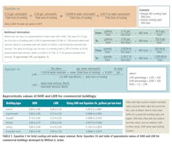
Equation 1
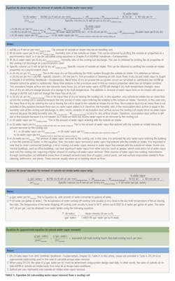
The first equation in our review (Table 1) is an approximate equation using 0.10 to 0.30 gal. of water per ton of air conditioning for every hour of operation.3 The value of 0.10 gal. per ton-hour occurs when the latent-heat ratio (LHR, the percentage of latent-heat removal) is 7.48 percent. The value of 0.30 gal. per ton-hour occurs when the LHR is 22.43 percent. Table 1 shows how LHR is calculated.
Table 1 also shows approximate LHR values for some commercial-building types. Kitchens have LHRs of 30 percent to 40 percent of the cooling-coil load; in other words, they would exceed the 0.30-gal.-per-ton-hour maximum. A kitchen with a LHR of 0.40, for instance, would produce around 0.5349 gal. per ton-hour.
What is unique about this equation is that it is easy to use and requires very little calculation time to get an approximation of the water removed by a cooling coil. It is helpful to know the cooling-coil design sensible-heat ratio (or LHR), which equates directly to gallons per ton-hour.
Table 1 provides gallons per ton-hour for different building LHRs. It is important to note that for most commercial buildings, cooling total load or tons varies significantly over the course of a year. Because the summer months generally are more humid and a lot of latent heat or water vapor comes in via outside-air intakes, the amount of water removed by a cooling coil will be greater during summer. At Memorial Hermann Medical Plaza in Houston, for example, the amount of water collected during summer (June, July, and August) is approximately 95,000 gal. per month; the remainder of the year, it varies from about 7,000 gal. to 42,000 gal. per month.3 In summary, then, if you want to predict monthly water collection using these factors, you need to know the average total cooling tons on an hour-by-hour or day-by-day basis.
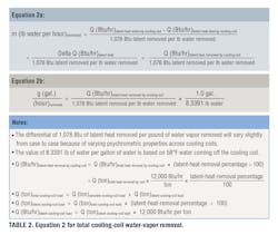
Equation 2
The second equation in our review (Table 2) can be found in a number of psychrometrics books. It is an approximate equation that yields good results, but requires knowledge of cooling-coil latent-heat removal (British thermal units per hour or latent-removal tons). Equation 1 requires only total coil load (tons) because it assumes the amount of latent-heat removal (which is why the factor varies from 0.10 gal. per ton-hour to 0.30 gal. per ton-hour). If you know only the total amount of heat (British thermal units per hour) removed by a cooling coil, you can estimate latent-heat removal by multiplying the total amount of heat removed by an assumed LHR. Approximate LHRs for certain building types can be found in Table 1. Determining monthly water removal with Equation 2 requires knowledge of latent-heat removal on an hourly basis for each month of the year.
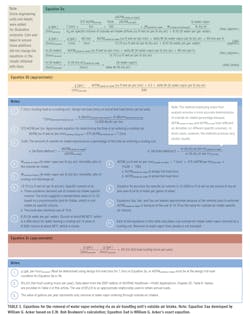
Equation 3
The third equation in our review (Table 3) is extrapolated from a book by E.W. Bob Boulware.4 It is a type of mass-flow analysis for calculating the amount of outside-air-intake water vapor removed by a cooling coil. It does not address other sources of water vapor in buildings.
The accuracy of equations 3ab and 3ac can be improved by:
• Using the specific volume (cubic feet of wet air per pound of dry air) of air at outside-air-intake properties, rather than the specific volume of air entering the cooling coil. For Dallas, the outside-air-intake properties are 95°F dry bulb, 75°F wet bulb for a specific volume of 14.36. The book advocates a standardized value of 13.7 or 13.8 (see equations 3ab, 3ac, and 3b), which results in a loss of accuracy. Using the actual specific volume and actual cubic feet per minute (ACFM) of the outside-air intake in the following equation will produce an accurate value of the mass dry-air flow:
m (lb dry air per hr)outside-air intake = ACFM (cu ft wet air per min)tested outside-air intake × (1 ÷ specific volume [cu ft wet air per lb dry air])outside-air intake × 60 min per hr
• Using the mass dry-air flow of the outside-air intake in the following equation, which will produce an accurate mass water-vapor-removal rate:
m (lb water per hr)removed = m (lb dry air per hr) × (Woutside-air intake − Wcooling-coil discharge) lb water per lb dry air
• Using the more-exact volume-to-mass conversion of water of 8.3391 lb per gallon. The book uses the value of 8.33 lb per gallon.
• Using actual outside-air-intake ACFM, if known, instead of the equation in Note 8 in Figure 3.
With these changes, the approximate equation becomes exact Equation 3ad. Next month, in Part 2 of this article, we will discuss why this mass-flow equation works.
Equation 3b, also from the book, is less accurate than Equation 3a because it assumes a standard outside-air-intake specific volume of 13.3333, which is lower than actual outside-air specific volume typically. Actual outside-air specific volume can be found on most psychrometric charts by plotting outside-air properties (dry bulb and wet bulb, dry bulb and relative humidity, or dry bulb and humidity ratio).
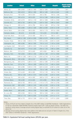
Equation 3c is used to calculate the amount of outside-air-intake water vapor removed by a cooling coil annually. This equation requires multiplication of an input value of gallons per hour removed by equivalent full-load cooling hours per year (EFLCH). If the gallons per hour in Equation 3a or Equation 3b is used, the gallons per year will represent only the outside-air-intake water vapor removed.
Values of EFLCH for four building types—school, office, retail, and hospital—in 35 U.S. cities are given in Table 4. This is a great procedure for estimating water removal without going through many hours of calculation. The alternative is to calculate the gallons removed each hour the air conditioner operates and add them, which may involve 1,000 to 5,000 individual calculations, depending on the location and annual operating hours of the air conditioner.
Equation 4
The fourth equation in our review (Table 5) is taken from mass-flow-analysis equations, which are accurate equations. It requires use of the ACFM of outside-air-intake airflow, which can be obtained from a field test or from building design-load analysis.
Equation 4c is approximate because of the use of EFLCH (hours per year). When using Equation 4c, you need to use building-design-load-analysis ACFMoutside-air intake to calculate gallons per hour.
It is very important to note that when using Equation 4a or 4b, the ACFM must be at the psychrometric properties and specific volume of the outside-air intake. In other words, you cannot calculate dry-air mass flow using the ACFMoutside-air intake and specific volume of the air at the inlet to a cooling coil. Also, when you have two airflows, such as outside-air intake and building recirculation-duct return air, mixing together, you cannot add the ACFMs together. You can, however, add the dry-air mass flows of the two airflow streams to get the dry-air flow of the mixture. You also can add the two water-vapor mass flows to get the water-vapor mass flow of the mixture.
What is unique about equations 4a and 4b is that we are analyzing only outside-air-intake mass dry-air flow and mass water-vapor flow through the cooling coil. Normally, outside-air-intake flow is mixed with recirculation-duct return-air flow, which makes up cooling-coil-inlet mass dry-air flow and water-vapor flow. In this case, however, outside-air-intake and recirculation-duct airflows are analyzed separately across the cooling coil, which is allowed in mass-flow analysis. In this equation or process, we assume the only source of water vapor entering the building is the outside-air intake. Because the recirculation-duct return air has no added water vapor (its humidity ratio is equal to that of the cooling-coil discharge), it can be left out of the calculations. This occurs only when the lone source of water vapor is the outside-air intake. This will become very clear next month, when, in Part 2 of this article, we analyze equations 4a and 4b using a complete building-air-system airflow diagram.
References
- EPA. (2007). Process water efficiency: Healthcare - Top 5 green building strategies. EPA Publication 909-F-07-001. Retrieved from http://www.epa.gov/region9/waste/p2/pdf/water-final-071126.pdf
- Hernandez, P. (2011, September 1). Reusing air conditioning condensation to save water. Houston Public Media. Retrieved from http://www.houstonpublicmedia.org/news/1314915796/
- Guz, K. (2005, June). Sustainability: Condensate water recovery. ASHRAE Journal, pp. 54-56.
- Boulware, E.W. B. (2012). Alternative water sources and wastewater management (ch. 3). New York: McGraw-Hill Professional.
The president of Acker & Associates, a consulting engineering firm he founded in 1996, and a longtime member of HPAC Engineering’s Editorial Advisory Board, William G. Acker is considered an expert in psychrometrics, mass-flow analysis, and water-vapor transmission. Along with colleague Nels E. Strand Jr., he has developed more than 50 computer programs used to solve problems, determine energy flows, and calculate air-pollution emissions. The programs are highly recognized by engineers with The National Institute for Occupational Safety and Health, ASHRAE, the North American Insulation Manufacturers Association, the National Roofing Contractors Association, the Association of Energy Engineers, and the U.S. Environmental Protection Agency. He can be reached at 920-465-3548.
Did you find this article useful? Send comments and suggestions to Executive Editor Scott Arnold at [email protected].

