Low-Temperature-Chilled-Water Plants Revisited
According to the U.S. Energy Information Administration’s Commercial Buildings Energy Consumption Survey (CBECS), despite a 14-percent increase in total buildings and a 22-percent increase in total floor space, U.S. commercial-building energy use increased just 7 percent from 2003 to 2012.1 Meanwhile, the national average energy-use intensity (EUI) for U.S. commercial buildings in 2012 was 80 kBtu per square foot per year, the lowest level reported since the CBECS was begun in 1979.
Despite these gains, there is much room for improvement concerning the efficiency of existing commercial buildings. ANSI/ASHRAE/IES 100-2015, Energy Efficiency in Existing Buildings, sets energy targets that, if fully implemented, would lower the national EUI to around 68 kBtu per square foot per year. ASHRAE 1651-Research Project, “Development of Maximum Technically Achievable Energy Targets for Commercial Buildings: Ultra-Low Energy Use Building Set,” determined that if all new buildings were designed and operated with the very latest energy-efficiency measures, a weighted average EUI of 28.5 kBtu per square foot per year could be achieved, depending on building type.
We are a long way from making all commercial buildings net-zero, but there are opportunities to improve the performance of buildings that use chilled water for comfort cooling. This article will discuss the design and operating condition of chilled-water plants serving large-office, hospital, large-hotel, and secondary-school U.S. Department of Energy (DOE) protocol buildings by revisiting a common understanding of supply chilled-water-temperature setpoint.
Chilled-Water-Supply Temperature and Range
In 1998, Kirsner2 concluded a chilled-water-supply temperature of 42°F and a differential temperature of 14.3°F, as opposed to a chilled-water-supply temperature of 45°F and a differential temperature of 10°F, would result in a net energy penalty for chilled-water plants with pumping heads below 100 ft total design head (TDH). Kirsner went on to say the potential for energy savings from chiller plants designed to a 42°F chilled-water-supply temperature and a 14.3°F differential temperature occurs at full design flow, but may not exist at partial flow—even in systems with more than 100 ft TDH; energy savings depend on the response of the pumping system to part-load conditions.
To allow an understandable comparison between the two chiller-plant-operation schemes, a number of assumptions were made. For today’s chiller systems, the assumptions no doubt would be different.
Chiller-Plant-Study Assumptions
In the Kirsner study:
- All chillers used R-123 refrigerant.
- All single-stage chillers used gearboxes.
- Evaporator shell and tube arrangement did not change between a design of 45°F chilled-water-supply temperature and 10°F differential temperature and a design of 42°F chilled-water-supply temperature and 14.3°F differential temperature.
- The water-side tube-interior-film heat-transfer coefficient would change at reduced flows, increasing resistance to heat transfer and causing larger refrigerant approach temperatures.
- Compressor adiabatic efficiency was fixed at 82 percent.
- Compressor motor efficiency was fixed at 95 percent.
- Bearing- and shaft-seal losses were assumed to be equal among all chiller-compressor types.
- All hydronic components—pipe, valves, coils, strainers—remained unchanged with the change in supply and differential temperatures.
Given all of these assumptions and chiller-performance data from two manufacturers, Kirsner found a range of 0.0133 to 0.053 kW per ton per degree Fahrenheit to be the penalty for lower supply chilled-water temperature. For the analysis, the conservative value of 0.0150 kW per ton per degree Fahrenheit was used.
Chilled-Water-Pump Energy Savings
Kirsner also made assumptions about change in the hydronic system. With a 14.3°F differential temperature, he assumed no change to the hydronic system, making the required chilled-water flow about 70 percent of that with a 10°F differential temperature. He assumed the new head would be 52 percent of the original design and power 36 percent. In his analysis, the question was whether this large reduction in pumping power at design conditions exceeded the chiller energy penalty at a 42°F chilled-water-supply temperature and a 14.3°F differential temperature.
Kirsner concluded one is better off maximizing chiller efficiency using a higher chilled-water temperature at pumping heads below 100 ft TDH. Even if a system uses variable flow, the chiller penalty, in terms of kilowatts (not kilowatts per ton), for supplying 42°F chilled water instead of 45°F chilled water will diminish linearly and in direct proportion to part load. The instantaneous pumping-power savings will diminish more rapidly than the chiller penalty at reduced loads. Thus, it makes sense to favor improving chiller efficiency over improving pumping power.
How Chillers and Chiller Plants Have Changed
Nineteen years after the publication of Kirsner’s article, much regarding chiller-plant design and operation is or soon will be different. Before long, no new chillers will use R-123; the majority will use another refrigerant. Compressors more commonly are using variable-speed drives and direct drive rather than gearboxes. Some chillers are even running without bearing losses. Compressors and their motors are more efficient and more closely matched to duty. Variable primary flow is more common than constant-volume or primary/secondary hydronics. Large chilled-water plants are being designed with higher temperature ranges—ANSI/ASHRAE/IES 90.1, Energy Standard for Buildings Except Low-Rise Residential Buildings, now requires cooling coils to be selected at a differential temperature of 15°F.
Effect of Building Type on Potential Savings From Lower Chilled-Water-Supply Temperature
With improvements in full-building energy-analysis tools, various conditions of plant operation can be simulated and compared to determine annual energy savings. The question is whether changes in technology affect the conclusions drawn in 1998. Does operating a chilled-water plant at 42°F and a large temperature differential save energy in large buildings?
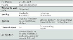
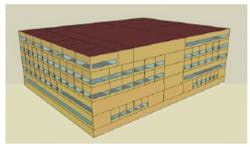
To demonstrate the effect of low-temperature air and low airflow, a standard large inpatient hospital in Chicago was modeled using DOE software EnergyPlus 8.4.0 (Table 1). This building type was chosen for its complicated HVAC system and because it is likely to need low-temperature air for special spaces. The model was created by Pacific Northwest National Laboratory and National Renewable Energy Laboratory under contract with the DOE. It, along with several other models, called protocol buildings, is used to determine energy-efficiency performance according to the 2013 version and subsequent editions of ANSI/ASHRAE/IES 90.1. The model was modified to simulate performance at two operating conditions:
- Baseline 45°F/55°F chilled water was used to create a fixed setpoint of 55°F air delivered to variable-air-volume (VAV) boxes with hot-water reheat serving the patient-care areas. In non-patient spaces, leaving-air-temperature setpoint was allowed to vary from 55°F to 60°F when appropriate.
- Low-temperature air (45°F to 49°F in patient areas and 45°F to 60°F in non-patient areas) with reheat was created using the corresponding low chilled-water temperature (42°F/57°F). Because this change required cooling coils to be significantly larger, both air-pressure drop and water-pressure drop increased.
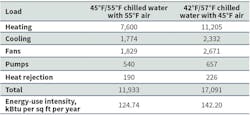
Energy analysis revealed lowering supply-air temperature to 45°F to 49°F caused the amount of reheat energy needed to increase dramatically (Table 2). Generating a 15°F differential temperature required a coil with more rows and a higher water-pressure drop, which increased the pump power, as shown in Table 2. It should be noted the main reason for the large increase in heating energy was the large minimum VAV position required for this building type. Some spaces are required to maintain a fixed minimum air-change rate, which can be reduced only when the space is unoccupied. In these simulations, the total airflow did not decrease. This was partially because of the required fixed minimum air volume and partially because of the draw-through arrangement of the air handlers causing the 45°F air produced by the cooling coil to increase to 49°F or 50°F. The protocol-building model contained calculated fan heat rise in the air stream.
Although hospitals may require a 30 percent or greater minimum box position, other buildings may get by with a smaller minimum position. All buildings with any amount of minimum box opening when a space is occupied will show an increase in reheat energy because of lower primary air temperature.
Several changes to the protocol model were necessary to ensure the chiller plant and air handlers behaved appropriately. When first run, the protocol model showed the chiller plant delivering to the cooling coils water at temperatures above those produced by the chillers. The plant model came with the chilled-water plant in a primary-secondary loop arrangement with pumps on each loop. An idiosyncrasy of the EnergyPlus software is that it requires hydronic loops to have bypass pipe around chillers. A primary pump can have a higher flow rate than chillers, especially when only one chiller is running. Warm water bypassing an active chiller increases the temperature of the chilled water leaving the supply side of a plant. Another issue with the model was that common pipe in loop connections will flow water in either direction, so, whenever secondary flow increases beyond primary flow, supply-water temperature rises. Here, the model does a good job of simulating many primary-secondary plants that have flow-imbalance problems. The result of this higher supply-water temperature is a reduction in the ability of cooling coils to generate a good water-temperature difference and a low supply-air temperature. This analysis, however, needed the coils to have the benefit of the coldest-possible water to create a large temperature difference and a reduced airflow requirement. Modifications were necessary to make the model deliver water to the coils at the same temperature created by the chiller.
Changes to the Protocol Hospital Model
The following changes to the hospital model were made:
- Chilled-water distribution was converted to variable-primary flow.
- Chilled-water-pump flow was changed to provide either a 10°F or a 15°F temperature difference.
- The chillers were selected and sized to match the new flow and temperature range.
- The chillers were set to no-flow control (EnergyPlus has several flow-control options; setting a chiller to no-flow control means flow will be set by plant requirements). One consequence of not allowing a chiller to limit its flow was discovered when one chiller staged off. Whatever system flow happened to be at a given time, chiller shutdown was shifted to the remaining operating chiller. This “overpumping” of the remaining chiller smoothed the transition from two chillers to one and vice versa. Obviously, the chillers needed to be sized to accommodate the extra flow without exceeding the maximum flow limitation.
- The remaining pump was set to variable flow, and the head was set to accommodate increased resistance from the modified cooling coils (when a new coil was selected for a 15°F differential temperature, the increase in water-pump head was dramatic).
- The coils were re-sized to a 10°F or a 15°F water-temperature difference. This was the most difficult of all of the modifications to the model. The coils were selected using the coil manufacturer’s computer selection tool. The coils’ physical description then was entered into the EnergyPlus Coil:Cooling:Water:DetailedGeometry object. Many iterations of coil design were needed to achieve the air-temperature and water-temperature differences. With some coil parameters, autosizing was not possible, as the results were highly unusual and physically impossible.
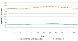
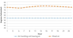
After these modifications, the air handlers began to perform as intended on the design-day run (figures 1 and 2). In Figure 1, the leaving-air temperature is near 45°F throughout the day; in Figure 2, it is 55°F. Patient rooms, however, require a minimum air-change rate based on room volume to prevent the quantity of air from dropping. Because the supply-air temperature is lower, there needs to be additional reheat energy to maintain room temperature at part-load conditions.
Leaving-chilled-water temperature has an effect on the performance of chillers. When the condensing temperature was the same from one scenario to the other, the lower leaving-chilled-water temperature would increase the lift on the chiller, as well as energy use. The increased energy use of the chiller, coupled with the increased energy use of every other chiller-plant element and the air-handling units, made this a questionable approach to reducing energy consumption.
As in Kirsner’s study, assumptions were made in this analysis: The default chillers in the protocol building use R-134a, modern compressor efficiencies are better now than in 1998, and the penalty from the higher lift does not have to be estimated from manufacturer’s data and applied uniformly over the year. Using the default chiller-performance curves from the protocol building (ANSI/ASHRAE/IES 90.1 minimum efficiency), the software will calculate the actual performance penalty at each time step of the simulation.
Kirsner assumed a chilled-water pump would use less energy with a 15°F differential temperature than it would with a 10°F differential temperature. What Kirsner did not account for was the change in head created by the need for a coil capable of a 15°F water-temperature increase. In this simulation, the increase in head was substantial, so there was an increase in chilled-water-pump energy. The coils not only had a larger temperature range to achieve, they had to achieve it at a relatively large outside-air percentage, which accounted for some of the large increase in water head.
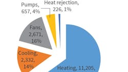
The consumption of all five energy users in the cooling plant increased. Heat rejection increased because of the higher cooling energy and the higher reheat energy (the chiller-efficiency penalty and the higher cooling load from the additional reheat). Fan and pump energy increased because of the higher static-pressure and water-pressure drop in the cooling coils.
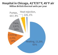
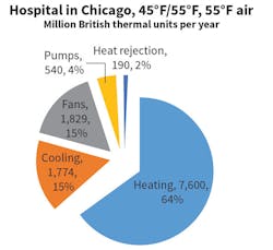
Figure 3 shows the DOE protocol building with the aforementioned corrections.
Health-care applications often are the reason for driving leaving-chilled-water temperature down to 42°F or below. Unfortunately, health-care applications, especially hospitals, have uniquely high minimum outdoor-air and total-airflow requirements that do not allow a large turndown of air at most thermal zones. VAV boxes often have 30-percent-minimum-airflow limits, and some designers typically will use 50-percent minimum limits. This alone explains why delivering air at lower temperatures drives up annual heating energy.
Life-cycle-cost analysis is a great tool to aid pipe sizing, as shown by Taylor.3 But pipe size is only part of the problem when calculating total pump head. Coil selection is a critical problem that can negate most or even all of the potential savings from reduced flow because of greatly increased water-pressure drop at coils. Coil sizing and selection affects both leaving-chilled-water temperature and differential temperature.
High-head-coil location also affects total distribution-pump head. High-head coils placed some distance from a plant will directly affect pump design head. Reduced flow from higher delta-T can mean smaller pipe size, with the flow at the top end of the flow range for that pipe size.
Part of the reason for reduced chilled-water temperature in health-care facilities is the special case of a space type, such as operating room, requiring particularly low temperatures. These spaces not only require low temperatures, they need large volumes of air at all times, regardless of the delivered-air temperature. When cooling coils are required to generate a larger water-temperature range than the Air-Conditioning, Heating, and Refrigeration Institute-standard 10°F, they tend to be sized and selected with more rows and a larger air-pressure drop, which causes fan power to rise.
What to Do
A hospital using more energy, especially reheat, in service of a few special rooms is not ideal. What most experienced designers do is not penalize the chiller plant with 42°F water, but stick with typical 44°F/54°F design (or 44°F/59°F when complying with ANSI/ASHRAE/IES 90.1-2016) and place a direct-expansion (DX) coil in series with the standard chilled-water coil in a dedicated air handler serving operating rooms. The added pressure drop through the DX coil can be reduced easily with a bypass damper. The fan motor still needs to be sized for the added pressure, but the pressure is not present all of the time. Concerns about closing off the DX coil when the refrigerant compressors are running can be addressed easily by not putting a face damper on the DX coil. When the bypass damper is opened, airflow will be divided between the coil and the damper, reducing pressure drop. Safety controls still will be needed to stop the compressor when flow through the DX coil drops, however.
The point being made here is not that low chilled-water-supply temperature and high differential temperature necessarily is a bad idea. Certainly, this design concept works well in some applications, as shown by Taylor. The point is that it does not always work and especially does not work in applications with fixed minimum airflow requirements plus a need to maintain comfortable environments. Buildings must be analyzed for their unique flow, pressure, and energy use. As the industry requires greater efficiency in even the most complicated building types, design professionals need to carefully consider the implications of what at first may seem to be a good idea, but turn out to be just the opposite.
Conclusion
Undoubtedly, there are buildings that would benefit from lower chilled-water temperature and higher chilled-water differential temperature. These buildings are characterized by the ability to reduce airflow, cooling coils that do not increase water head as much as the coils in this project, and air handlers that are variable-airflow without reheat.
For this analysis, a hospital in Chicago was modeled to determine potential energy savings from reduced chilled-water-supply temperature and delivered-air temperature. The results are shown in figures 4 and 5. Increased energy use was seen throughout the HVAC system with colder water and air. Thus, the conclusions of the Kirsner study are confirmed. In particular, hospitals are among the building types that would not benefit from this approach to chilled-water-plant operation.
References
- EIA. (2016, March 18). 2012 commercial buildings energy consumption survey: Energy usage summary. Retrieved from http://www.eia.gov/consumption/commercial/reports/2012/energyusage/index.php
- Kirsner, W. (1998, January). Designing for 42°f chilled water supply temperature—Does it save energy? ASHRAE Journal, pp. 37-42.
- Taylor, S.T. (2011, December). Optimizing design & control of chilled water plants, part 3: Pipe sizing and optimizing ∆t. ASHRAE Journal, pp. 22-34.
Richard D. Hermans, PE, HFDP, is senior manager, mechanical engineering, for AECOM. At the time of authoring this article, he was director of training and advanced applications for Daikin Applied.
Did you find this article useful? Send comments and suggestions to Executive Editor Scott Arnold at [email protected].
