CFD Analysis Can Confirm Fabric Duct Ventilation Designs

By MICHAEL G. MORTENSEN, Engineering Manager, FabricAir
Most fabric duct ventilation designs may look good on the CAD screen. But computational fluid dynamics (CFD) analysis software designed specifically for fabric duct can confirm whether air distribution will perform to the engineer’s intent.
CFD analysis is more commonly used as confirmation of efficacy, rather than a detector of calculation errors. However, it can also detect potential ventilation shortcomings from unseen or unknown variables the engineer may not have considered.
A variable that many engineers may not totally account for in an air distribution design is boundary conditions. Window U-value, wall/roof R-value, wind load, infiltration, snow load, window solar gain, heat loads from people, machinery and other factors not directly associated with duct velocities and air distribution. CFD analysis can help reveal these factors that could affect temperature gradients, air mixing, distribution and other performance considerations.
Advances in Ventilation Design Sophistication
While there are many outsourced CFD services, manufacturers have recently introduced their own fabric duct-oriented software programs that have arrived at an opportune time. Ten years ago, engineers weren’t concerned with flow models and there were few retrospective requests for vent sizes and positioning. But the HVAC engineering design industry’s air distribution training and technical knowledge has grown considerably since then.
Now, engineers want confirmation on a host of items, such as the velocity in the occupied zone or the effects that a six-degree delta T will have on air mixing and temperature gradients within the space. This sophistication is a result of building owners (and their tenants) requiring better IAQ, air comfort, and energy efficiency.
Another factor is the unprecedented building types that are air-conditioned today, such as warehouses or assembly plants. These newcomers present unprecedented challenges such as high ceilings, more outdoor air infiltration, industrial process heat loads and other factors that challenge engineers that previously may have only had ventilation design experience with offices, hospitals or other common air conditioning applications.
A CFD analysis can prove that a fabric duct with the correct engineering will remedy any ventilation challenge, such as overheated air or a circulation dead zone. Or in a large area with high ceilings, it can prove that the correctly engineered fabric duct will cover the occupied zone adequately. But such analysis isn’t reserved just for velocities or air distribution in the occupied zone. It can also detect induction, infiltration, air mixing and temperature gradients.
For example, infiltration can be detected in voids between a warehouse’s truck and the open dock unloading area. Plus, the information might be helpful in determining the usefulness of an additional linear duct running across all the dock openings in an air curtain type of function.
Proving an unsatisfactory design will lead to changes, such as repositioning the fabric duct or other minor adjustments. When the air coverage problem is more severe and can’t be solved, then the last resort is changing the fabric duct’s flow model–essentially starting over for that room area. A second CFD analysis can then be run.
Metal duct system designs are less critical, because the engineer’s airflow direction, velocity or mixing can sometimes be corrected by field-adjustments onsite. However, metal duct with registers every 8 ft. doesn’t always facilitate a comfortable airflow to the occupied zone. Typically, there are drafts under the registers and dead zones between the registers. On the other hand, fabric duct is designed by engineers and then custom-manufactured. The manufacturing is overseen by factory engineers to assure vents, airflow through the fabric’s permeability, and other features unique from metal duct are feasible. Fabric duct is known for comfortable, non-drafty velocities down to the occupied zone, mainly because of its variety of vents, most of which span the length of the duct for even air distribution.
The New Generation of Fabric Duct CFD Analysis
CFD analysis isn’t new, but software designed specifically for fabric duct ventilation designs is a recent development. So why use it? A good analogy is auto repair. A car owner has a choice of taking a car to an independent service company, possibly for a better price, or a dealership authorized by the car manufacturer, which is typically more expensive. Most car owners perceive a more competent service from the dealership, because their troubleshooting equipment, training and instruments are specifically designed for that brand and model.
The same is true in fabric duct CFD analysis. Obviously, some engineering firms have their own CFD analysis programs, but it may not detect fabric duct’s idiosyncratic differences from general air distribution.
The Best Application for CFD Analysis
The most popular applications for CFD analysis are:
- Office Buildings because they typically have many windows, heat generating office equipment and workers that add up to a substantial heat load. Air comfort is especially critical in offices;
- Sports Facilities and Warehouses have inherently large volumetric spaces and high ceilings, which complicate air distribution design;
- Aquatic Facilities are unique because of psychrometrics– thermodynamic parameter of moist air at a constant pressure. Typically, they also have fairly high ceilings. Today’s design trends include more windows that can introduce condensation if not properly bathed in supply air. Additionally, aquatic facilities are reputed to potentially cause respiratory symptoms in swimmers due to harmful gas chloramines congregation at the pool surface. Therefore, CFD analysis can be invaluable for designing enough air velocity above the pool surface to move chloramines toward return air inlets, but not excessively enough where it increases the pool evaporative rate. Natatoriums are a myriad of difficult environmental balances that CFD analysis can help solve.
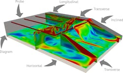
What is True 3D CFD Analysis
All fabric duct manufacturers offer free theoretical analysis sheets that are perhaps mislabeled as CFD. However, they aren’t considered true 3D CFD modeling. This method is advantageous for engineers that want a quick and simple, theoretical representation of where ventilation air will disperse and its velocity. They are often spreadsheet-based, two-dimensional X/Y axis graphs with airstream centerlines exiting ductwork without critical details, such as diffusion patterns, room air mixing and movement.
A few manufacturers off a true CFD modelling that are customized to each project and 90-percent more accurate than analysis spreadsheets. Their sophistication and comprehensiveness is comparable to CFD services offered by CFD consultants. They typically come in several levels depending on the project’s sophistication. The simplest true 3D CFD analysis levels are ideal for projects where supply air is parallel to return air when the system comprises up to two flow models. The most sophisticated levels can comprehensively analyze nearly anything an engineer can conceive. For example, they can demonstrate multiple flow models, multiple sectional cuts with reports of occupant comfort in specific locations, or an air movement overview seen in all dimensions regardless of room complexity. These packages typically include full animation, probes that provide a particular spot’s air velocity and temperature, plus analysis for external elements such as machine heat sources, wind and snow loads, movables and window panels.
CFD analysis should be a regular tool in the engineer’s design arsenal. It’s invaluable for confirming that an engineer’s design, which ultimately leads to satisfied building owners and occupants.
###
The author is engineering manager at FabricAir, a Denmark-based manufacturer of fabric duct and accessories with North American offices in Lawrenceville, GA. Mortensen has a mechanical engineering degree from Danmarks Tekniske Universitet/DTU. He recently oversaw FabricAir’s development of its CFD Service, the HVAC industry’s first and most sophisticated to date. He can be reached at [email protected].