Getting Real in the Chiller Plant: 30 Years Later
By GARY R. GABRIEL, P.E., Johnson Controls, Roswell GA
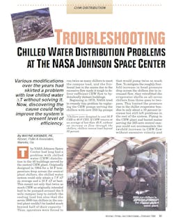
As a young professional engineer, I was lucky to be the helper to a really great mechanical engineer, Wayne Kirsner, P.E. During the summer of 1992, Wayne and I visited the NASA Johnson Space Center site to prepare an Energy Study. We came across the Great Chilled Water Delta T Saga that Wayne documented in his 1995 HPAC article. This is a great read.
Some 30 years later, I see that the HVAC design community has not lost enthusiasm for low gpm per ton chilled water plant design (high chilled water delta T design). Adding insult to injury, low gpm per ton condenser water is also seen entering the design mix.
Aggressive design to reduce first cost is taking place on the refrigeration “low” side of the equation by designing the chilled water side for low gpm per ton. Similarly, aggressive design is also taking place on the refrigeration “high” side of the equation by also designing the condenser water side for low gpm per ton.
Market pressures to reduce construction first cost are sure to factor in, as each low gpm per ton design choice reduces the construction cost of pipes and pumps. However, after the job is built, the customer suffers with increased chiller and pumping energy costs.
The biggest electric motor on the job is the chiller compressor motor. Compressor lift occurs between the leaving chilled water temperature and the leaving condenser water temperature. In practice, the battle against low delta T on the refrigeration low side is done by lowering the chiller set point to force additional heat transfer. This increases the chiller compressor lift.
Meanwhile, during the design the refrigeration high side has been raised by the increased temperature leaving the condenser. The refrigeration high side is further raised as condenser tube fouling occurs over time. Besides the bad news for the chiller energy waste, pumping energy waste mounts also.
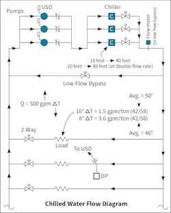
For example, on the refrigeration low side, the chilled water system is likely pumping as much as twice the flow at piping friction rates far greater than design. Similarly, on the refrigeration high side, extra condenser water is flowing due to extra chillers being operated as standard practice. Extra chillers are required to run to create a flow path for the beyond design chilled water flow in the chiller plant.
Question: What causes this low delta T on the chilled water system?
Answer: Impaired air to chilled water heat transfer.
Question: What causes this impaired heat transfer?
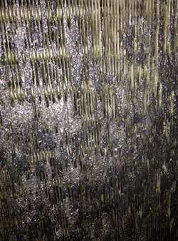
Answer: Airside fouling.
Question: Why does a fouled airside coil demand more chilled water flow?
Answer: At low delta T the coil is colder, forcing more air to water heat transfer, to achieve a nominal 55 degree supply air temperature.
Healthcare Applications
A hospital customer was dismayed to learn why two 18-degree chilled water delta T chillers would not load beyond 72 percent. The chillers had previously been provided as part of a “plan and spec” scope designed by a third party. Even with 38-degree supply chilled water, the best the system load could do was a 13-degree delta T (chilled water return temperature at 51 degrees). Besides the wasted investment in chiller capacity that could not be loaded, the ability to provide N plus one chiller plant response to the hospital was ruined. Energy performance suffered also.
As a remedy, we quoted replacing the chiller evaporator heads to convert each chiller evaporator from 3 pass to 2 pass to accommodate the doubled chilled water flow. The scope also included upsizing the primary chilled water pumps and upsizing the primary chilled water piping to accommodate the increased gpm per ton.
In planning and design of a brand new chiller plant, consider the following:
1. Designer prerogative will determine the chilled water supply temperature. Consider selecting the chiller at 42 degrees, but start out running it at 44 degrees (when all the heat transfer surfaces are new and clean). Later, if necessary, the chiller can be operated at 42 degrees or colder to force air to water heat transfer when everything is fouled. This is in context of a 55 degree supply air temperature;
2. Select the chiller evaporator with flow headroom. For example, avoid 3 pass evaporators, go with 2 pass instead. Select a 2 pass evaporator for nominal 12 feet pressure drop. Later, if the load is screaming for double the water, the pressure drop will “only” increase to 48 feet. As a side benefit, a 2 pass chiller evaporator is less expensive to manufacture and purchase than 3 pass. Also note that for a tall building, pump away from the chiller evaporator, to try to stay within the limits of a 150# evaporator. Otherwise, the expense of a 300# evaporator may be triggered;
3. Designer prerogative will determine the design chilled water delta T. Consider headering the VSD variable primary chilled water pumps, with a so called “N plus one” extra pump included (or at least footprinted). Consider sizing each chilled water pump at a 10 or 12 degree delta T, with an extra 20 feet head capability for good luck. Consider going up one chilled water pipe size in the plant. Later, the upsized chilled water pumps, in concert with running the N plus one pump, will resource the extra chilled flow needed when the load is screaming for water. Otherwise the plant is stuck running extra chillers to give the chilled water flow somewhere to go. Running the extra chillers causes an energy penalty because additional condenser water pumps are turned on (this hack is not possible in a one chiller plant);
4. Go with 3 gpm per ton for the chiller condenser, condenser water pump, and condenser water piping. Go with 2 pass on the chiller condenser. Later, the reduced condenser refrigerant head pressure that is resourced by this measure will be useful to counter the added lift penalty caused by the colder chiller setpoint, needed to force air to chilled water heat transfer when everything is fouled. Condenser tube fouling between annual cleanings drives up the condenser refrigerant head pressure also, further increasing chiller compressor lift requirement. Here is the link to Wayne Kirsner’s 3 gpm per ton article: http://kirsner.org/kce/media/pdfs/3_gpm_per_ton_chiller_condenser_water_flow.pdf;
5. Select the cooling tower at 3 gpm per ton, for a 10 degree delta T. Later, the cooling towers sized at traditional box size (not downsized) will be helpful to counter the added refrigerant lift penalty;
6. Take it easy on the chilled water coil airside face velocity at each air handling unit. Slower air at 450 to 480 feet per minute improves the air to water heat transfer capability when fouled, among other benefits. Airside fan energy savings occur from day one due to the lower design air pressure drop. Another advantage of slower air is reduced risk of cooling condensate carry over. For example, when the coil airside is clogged, airflow channeling causes pockets of extra high velocity air through the coil finned surface which whips the liquid condensate off of the coil, causing flooding in the air handling unit;
7. Provide OEM UV coil sanitation as part of each air handling unit selection;
8. Four row chilled water coils are not allowed. In contrast, at each air handling unit the minimum coil selection allowed should be 6 rows with 10 fins per inch;
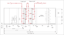
9. Consider providing two separate chilled water coils, arranged in series in the airflow. Similarly, chilled water would also be piped in series. Later, when the coil is fouled, the extra rows will offer some attempt at air to water heat transfer.
If the design and construction is already done, and you are stuck with a low delta T load mismatched to a high delta T chilled water plant, consider the following:
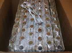
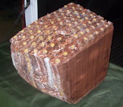
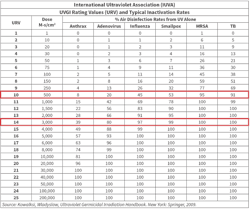
1. In application for a commercial building, improve the air to chilled water thermal exchange with PurgenixMatrix™ at an IUVA (International Ultraviolet Association) ultraviolet rating of 10, at each air handling unit, downstream of the chilled water coil. PurgenixMatrix™ will clean up the coil airside and will keep the chilled water coil airside clean which will allow air to water heat transfer to occur, reducing the demand for chilled water flow;
As an original skeptic of PurgenixMatrix™, and of UVGI (Ultraviolet Germicidal Irradiation) in general, during 2014 we had an industrial customer with a severely underperforming chilled water coil airside, due to oil based ink airside clogs. The normal course of action was air handling unit coil replacement, however we decided to do a case study with PurgenixMatrix™.
2. Keep the BAS (Building Automation System) in tune, using an Analytics Platform. At part load the chilled water system delta T should be better than design, not worse. Consider providing an Analytics Platform as an overlay on top of the BAS. The Analytics Platform is an Enterprise Management SaaS (Software as a Service) that, among other things, does continuous energy and comfort commissioning. Global rules are applied to identify system energy and comfort faults. For example, energy faults would include any chilled water control valve that is 100% open (everything should be throttling), or any pump VSD that is pegged at 100%;
3. Consider adding CPO (Central Plant Optimization) to the chiller plant. CPO is also an overlay on top of the BAS for BAS command (and BAS feedback) for energy optimization and real time reduction in total chilled water plant kw per ton. Note that in a hot and humid climate, CPO takes advantage of a 3 gpm per ton condenser water flow rate. This shows in real time that condenser water at 3 gpm per ton reduces the overall plant kw per ton. For example, the VSD condenser water pumps are observed at full output for lowest overall plant kw per ton. Similarly, CPO is all about reducing refrigerant and water lift (compressor lift and pump lift). CPO determines the optimal chilled water leaving temperature and the optimal condenser water leaving temperature, for the chiller. The chiller compressor VSD responds, the variable primary chilled water VSD pumps respond, and the cooling tower VSD fans respond, for the lowest chilled water plant kw per ton possible.
Conclusion
In this era of desired high performance building design, aggressive chilled water plant design choices are just cheapening the projects. Rather than saving energy, the recent design trends are wasting energy and causing operational problems.
In contrast, design choices that include the chilled water supply temperature, the chilled water delta T (chilled water gpm per ton), and the condenser water delta T (condenser water gpm per ton), present the opportunity for successful long term operation and energy savings. Also, the initial selection, arrangement, and protection of the air to water heat transfer coils can be made to allow reliable air to water heat transfer over the expected service life of the equipment.
Now in his ninth year with JCI, the author is a mechanical engineer and project development executive with three decades of HVAC, plumbing, and fire protection design experience. He can be reached at [email protected].
