Net-Energy Water Loops: A Clear Path to Net Zero
Achieving net-zero-energy usage has become an important factor in building design. The net-zero-energy concept analyzes the unique energy-use pattern of an entire building and reduces the energy footprint without sacrificing functionality or comfort. As the energy footprint is reduced, the impact of on-site renewable energy on the net-zero-energy goal increases.
HVAC systems for a net-zero-energy building must offer several fundamental characteristics: capture and effectively transport energy from one portion of a building to another, be scalable for any size building, provide a comfortable environment by heating and cooling individual temperature zones with maximum efficiency, and readily connect to and share energy with a wide range of HVAC and non-HVAC net-zero-energy-optimization strategies, as well as with on-site renewable-energy systems.
ASHRAE, along with several partner associations, has developed Advanced Energy Design Guides (AEDGs) to help designers achieve 50-percent energy savings toward a net-zero-energy building. As recognized in the AEDGs, a water-loop-heat-pump (WLHP) system achieves these core requirements. Beginning with a basic system of a water-source heat pump (WSHP) connected to a net-energy water loop, net-zero-energy strategies can be customized to take advantage of an individual building’s unique energy profile and the availability of on-site renewable energy. With these enhancements, a net-energy-water-loop system becomes a buildingwide energy transportation system that can achieve as much of the net-zero-energy goal as possible.
Water conducts and moves energy 10 times more effectively than air. Using air to transport energy throughout a building is restricted by not only the higher energy cost of air movement, but also the volume of physical space required for ductwork within a building structure. For the equivalent energy content, significantly smaller water pipes, which pass around and through floors more economically, can be used.
Using refrigerants to transport energy throughout a building is not practical, as compressor efficiency drops as refrigerant-tubing runs are extended. The movement of energy becomes limited to an individual refrigerant circuit used in variable-refrigerant-flow/variable-refrigerant-volume systems. Using a net-energy-water-loop system as a buildingwide energy transportation system provides a system with the lowest first cost and the greatest potential to maximize net-zero-energy building performance.
An Initial System
An initial net-energy-water-loop system is the WLHP system. Using non-insulated water piping to connect individual WSHPs, with each heat pump selected to match the load for a temperature zone within the building, transfers energy into and out of the water loop for use throughout the building. Each WSHP is controlled by a local temperature-control set point and can operate in cooling mode or heating mode independent of the rest of the WLHP system, allowing a net-energy-water-loop system to provide ideal comfort in each zone.
A WSHP in cooling mode will add energy to a water loop by moving heat from the local temperature zone and adding energy to the water loop from heat from the compressor and fan motor inside the WSHP. A WSHP in heating mode will move energy from a water loop into the local temperature zone and add heat from the compressor and fan motor to the local zone.
At minimum efficiencies established by ANSI/ASHRAE/IESNA Standard 90.1, Energy Standard for Buildings Except Low-Rise Residential Buildings, a WSHP’s cooling performance operates at an energy-efficiency ratio (EER) of 12.0. This means that for every 1 watt of electrical energy consumed, 3.5 watts of energy is moved from the local temperature zone to the water loop. The additional 1 watt of electrical energy consumed by the compressor and fan motor also is added for a total of 4.5 watts of energy transported into the water loop. A WSHP minimum heating performance operates at 4.2 coefficient of performance, (COP), which means that for every 1 watt of electrical energy consumed, 3.2 watts of energy is moved from the water loop to the local temperature zone. The 1 watt of electrical energy consumed by the compressor and fan motor also is added to the local temperature zone for a total of 4.2 watts of energy transported to the local zone.
In its most basic configuration, a net-energy-water-loop system is allowed to operate without any additional energy usage while the water-loop system temperature remains within a span of 60°F to 100°F. A heat-of-rejection device and a heat-of-addition device are required to condition the water loop to maintain this temperature range.
Because each WSHP operates independently, a net-energy-water-loop system is scalable to any size building, and the system increases efficiency during part-load operation. Energy is only used in a specific zone when an individual zone’s temperature rises or falls beyond the zone’s set point. Otherwise, the WSHP compressor is completely off. Additionally, with a motorized water valve interlocked with the compressor, all water flow to that WSHP is off, reducing the water-pumping energy for the water-loop system. As fewer units cycle on at a given time, less energy is required to maintain the temperature span of a net-energy-water-loop system.
Optimization Strategies
Optimization strategies can be employed to achieve as much of a 100-percent-net-zero-energy design as a building’s characteristics and a customer’s budget allow. For example, increasing efficiency of individual WSHPs is one optimization strategy with a low first cost. Upgrading each WSHP to a 21.6 EER and 6.0 COP immediately reduces electrical energy consumption of each local temperature zone and reduces the energy required to maintain the temperature span of a net-energy-water-loop system. From the earlier example of calculating energy for the cooling mode based on a 12.0 EER, a WSHP with a 21.6 EER would reduce the electrical energy input from 1 watt to only 0.56 watt to move the same 3.5 watts of energy from the local temperature zone to the water-loop system.
A popular optimization strategy is using a net-energy-water-loop system to provide energy to a domestic-hot-water system. Adding indirect hot-water storage tanks to a domestic-hot-water loop allows a water-to-water heat pump to move energy from the WLHP system to the domestic-hot-water-loop system, all while maintaining the required double-walled separation between refrigerant and potable water normally required by local building codes. By increasing the volume of the domestic-hot-water system, the water-to-water heat pump and associated equipment required to move energy to the domestic-hot-water system become greatly reduced.
Domestic-hot-water systems generally are sized for recovery from peak-water-flow usage. In commercial-building and hotel applications, however, these domestic-hot-water systems normally have long time periods of little or no flow. A very small water-to-water heat pump can move an immense amount of energy overnight to preheat hot water in storage tanks, which satisfies the large volume of hot water required by a hotel for morning showers. Eliminating large, instantaneous heating equipment—and its associated energy consumption—from a domestic-hot-water system offsets the costs of implementing this optimization strategy while moving the building closer to net-zero-energy operation.
Another optimization strategy involves capturing and transporting energy leaving the building in exhaust air. Energy captured by a net-energy-water-loop system is used to pre-heat outside makeup air. The same transportation system can be reversed to remove energy from makeup air any time outside air requires cooling. In either direction, the energy can be transported anywhere in a building once it is transferred to the water-loop system. A dynamic run-around loop is a possible method of utilizing exhaust-air energy effectively.
The utilization of on-demand ventilation using carbon-dioxide sensors modulates the amount of outside makeup and exhaust air. Because these values continue to change, fixed-capacity energy-recovery devices do not offer the most efficient energy transportation. Using a combination of multi-compressor water-to-water heat pumps, water-to-air coils (mounted in exhaust-air ducts and outside makeup-air ducts), and small variable-frequency-drive water pumps, energy can be readily moved between exhaust air, makeup air, and a net-energy-water-loop system. By staging the compressors and modulating water flow to the water-to-air coils, the run-around loop energy follows the demand of the ventilation system. When tied to a central building control system, additional heat recovery from exhaust air can be activated when any other net-zero-energy process, such as the domestic-hot-water system described in the previous paragraph, needs additional energy.
Net-zero-energy strategies with a central net-energy-water-loop system are not limited to HVAC and domestic hot water. Maintaining a separate process-water-loop temperature is another effective way to use energy. A separate process water loop can be used for radiant heat in the slab of a garage or storage facility or for snow melt under parking lots, sidewalks, bridges, and even storm-water drain pipes. A process-water loop also may be needed in buildings in which a manufacturing process is located directly on the other side of a wall from conditioned office space.
Further Efficiency Enhancements
A net-zero-energy design goal provides many opportunities for maintaining the temperature span of a net-energy-water-loop system. Adding a heat-of-rejection device, such as a fluid cooler, and a heat-of-addition device, such as a boiler, is simple. However, as other net-zero-energy strategies are employed, more energy-efficient means are available to maintain the water-loop-system temperature span.
By adding insulation to the water pipe, the lower end of a net-energy-water-loop temperature span can go as low as 20°F. With this wider operating range, energy can be moved in and out of many sources to maintain the water-loop temperature span. For example, an indoor ice-skating rink can use a net-energy-water-loop system to transfer energy from ice in the rink to forced-air heating in the seating area. Golf-course clubhouses can use net-energy-water-loop systems to transfer energy between the conditioned space of the clubhouse and sprinkler water before fairways and greens are watered.
Additional energy can be added to a net-energy-water-loop system from self-contained refrigeration products within a building. In multi-use buildings, refrigerated and freezer cabinets in restaurants and grocery stores can be connected to a water-loop system. In hotels, ice-making machines can be connected to a water-loop system. The added bonus of this strategy is all of these compressorized devices operate more efficiently and at lower sound-power levels when water-cooled.
On-site renewable-energy resources can be readily connected to a net-energy-water-loop system. Solar panels are easily adapted to add energy to a system. On-site electrical-generation-capacity requirements are reduced because of lower electrical consumption and lower electrical peak loading of a WLHP system, making biomass and wind-turbine systems more affordable. The waste heat produced generating onsite electrical energy using biomass systems also can be moved into a net-energy-water-loop system.
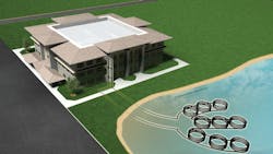
The most popular on-site renewable-energy resource for a net-energy-water-loop system is the earth, in the form of a closed loop either underground or at the bottom of a man-made pond or lake. Many buildings operate below 50 percent of their peak load for as much as 90 percent of their annual hours of operation, making the choice of a hybrid ground-loop system an economical renewable-energy strategy.
A traditional 100-percent-ground-loop system can be used to maintain the temperature span of a net-energy-water-loop system without any additional energy sources and is widely recognized as the most energy-efficient HVAC system available. However, a 100-percent ground loop needs to be large enough to dissipate energy from the building into the ground for 30 years without a buildup or drop off in energy in the ground. The physical land area required and installed costs of a 100-percent ground loop can become a design concern. Installing only 50 percent of a ground loop still allows the temperature span of a water-loop system to be maintained with a free source of energy for heat of absorption, and a free sink for heat of rejection for almost 90 percent of annual run hours. One-hundred-percent-ground-loop systems may be impractical for a commercial property of a certain size. A 50-percent-ground-loop design located underneath a building, a parking lot, or a green space provides almost the same net-zero-energy benefits of a 100-percent ground loop while requiring less than half the property size.
Conclusion
Net-zero energy plays a significant role in designing new buildings and renovating older buildings. Reaching 50-percent energy savings toward a net-zero energy building using a WLHP system is detailed in the current AEDGs. Beginning with a WLHP design, a net-energy-water-loop system can be customized to take advantage of a building’s unique energy profile, and on-site renewable energy, such as a hybrid ground loop, can readily be adapted to a net-energy-water-loop system. Combining this flexibility and low first cost, water-source heat pumps connected to a net-energy-water-loop system offer an economical design path to a net-zero-energy building.
As western region sales manager for the commercial sales group of WaterFurnace International Inc, Alan Niles is responsible for selecting, training, and managing commercial representatives in trade areas west of the Mississippi River. He is an active member of ASHRAE and an ASHRAE Distinguished Lecturer who has been presenting at local, regional, and national trade shows and meetings of ASHRAE chapters, providing technical assistance to architects and engineers in their design of high-efficiency heating and cooling systems, for more than 25 years. Also, he is a member of the International Ground Source Heat Pump Association. He holds a bachelor’s degree in mechanical engineering from the University of Oklahoma.
