How to Calculate Humidification Loads
Most humidifier manufacturers have software to help size and select humidification equipment. Still, it is important to understand the theory behind calculating humidification loads. This article demonstrates three ways to calculate humidification loads and explains how designing a system to reduce steam loss can conserve energy and water.
CALCULATING HUMIDIFICATION LOADS
There are three methods of calculating humidification loads: natural ventilation, mechanical ventilation, and economizer cycle.
Natural-ventilation method. Generally, a humidification load is based on the amount of air entering a building or space. In buildings without mechanical-ventilation systems, humidification loads usually are calculated using the air-change method. Buildings can be classified by the number of air changes per hour (ACH); typical air-change rates are 1 to 2, depending on the degree of air infiltration. For noncritical applications, 1½ ACH should be used for load calculations. (For critical applications and more information on calculating air infiltration, see Chapter 27, “Ventilation and Infiltration,” of “ASHRAE Handbook—Fundamentals.”)
To calculate the humidification load for a 120-ft-long-by-80-ft-wide-by-12-ft-high warehouse in which the desired conditions are 70°F and 50-percent relative humidity (RH), the entering conditions are 10°F and 45-percent RH, and ACH is 1:
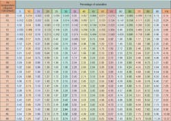
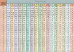
- Find the moisture content of the desired conditions (Table 1). (Air with a temperature of 70°F and 50-percent RH corresponds to a moisture content of 3.44 lb per hour per 100 cfm.)
- Find the moisture content of the entering air. (Air with a temperature of 10°F and 45-percent RH corresponds to a moisture content of 0.30 lb per hour per 100 cfm.)
- Determine the moisture to be added in pounds per hour per 100 cfm by subtracting the moisture content of the entering conditions from the moisture content of the desired conditions. (For example, 3.44 lb per hour per 100 cfm - 0.30 lb per hour per 100 cfm = 3.14 lb per hour per 100 cfm.)
- Determine the quantity of air to be humidified by multiplying the total cubic feet of the space by the ACH and dividing by 60 min per hour. (For example, [120 ft × 80 ft × 12 ft × 1 ACH] ÷ 60 min per hour = 1,920 cfm.)
- Determine the humidification load by multiplying the quantity of air to be humidified by the moisture to be added. (For example, [1,920 cfm ÷ 100 cfm] × 3.14 lb per hour = 60.29 lb per hour.)
Mechanical-ventilation method. The mechanical-ventilation method works best when the volume of outside air is at least 10 percent. When outside-air volume is below 10 percent in a mechanically ventilated system, the building may not be pressurized sufficiently to stop air infiltration. Therefore, actual outside-air volume may be greater than expected, and the calculated humidification load may not meet desired conditions.
To calculate the humidification load for a printing plant in which the desired conditions in the space are 70°F and 50-percent RH, the outside entering conditions are 10°F and 45-percent RH, and a mechanical ventilation system circulates air at 9,000 cfm, of which 25 percent is outside air using the mechanical-ventilation method:
- Complete the first three steps of the natural-ventilation method: determine the moisture content of the desired conditions, the moisture content of the entering air, and the moisture to be added in pounds per hour per 100 cfm.
- Determine the quantity of air to be humidified by multiplying the total air circulation by the percentage of outside air. (For example, 9,000 cfm × 25 percent = 2,250 cfm.)
- Determine the humidification load by multiplying the quantity of air to be humidified by the moisture to be added. (Using the same numbers given in the natural-ventilation example, [2,250 cfm ÷ 100 cfm] × 3.14 lb per hour = 70.65 lb per hour.)
Economizer-cycle method. Many year-round air-conditioning systems use economizer-cycle control. Economizer cycles use cool outside air instead of mechanical cooling to maintain building temperature.
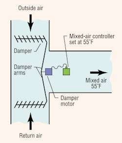
Figure 1 shows a typical application in which a mixed-air controller positions a modulating damper motor, which adjusts the outside-air intake and return-air dampers. Note that the dampers are opposing—as one opens, the other closes—to maintain a mixed-air temperature of 55°F as the outside-air temperature rises and falls.
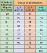
When the outside-air temperature rises to 55°F (100-percent outside air), the outside-air damper returns to a minimum setting (usually about 10 percent), and mechanical cooling takes over. Table 2 shows how outside-air percentages change with varying outside- and mixed-air temperatures. As the outside temperature rises, the ratio of outside air to return air increases.
For example, to cool return air to 55°F, 50 percent of outdoor air can be admitted at 40°F, but only 17 percent of outdoor air can be admitted at -20°F (Table 2). The warmer the outdoor-air temperature (below 55°F), the more air that can be admitted.
The formula for determining the quantity of outside air in an economizer cycle is:
V2 = VAH ÷ ([A ÷ B] + 1)
where:
VAH = V1 + V2
V1 = volume of return air (cubic feet per minute)
V2 = volume of outside air (cubic feet per minute)
A = temperature difference between mixed air and outside air
B = temperature difference between return air and mixed air
Consider an economizer-cycle system in which the outside air is 20°F, the return (room) air is 70°F, the mixed air is 55°F, and the total air is 12,000 cfm:
To solve using the economizer-cycle method:
A = 55°F - 20°F = 35°F
B = 70°F - 55°F = 15°F
VAH = 12,000 cfm
V2 = 12,000 cfm ÷ ([35°F ÷ 15°F] + 1) = 3,600 cfm of outside air
To document outside-air quantity at various points (typically 10°F intervals) over a range of outside-air temperatures, create a table using this formula. Table 2 shows percentages of outside air at a consistent 70°F room temperature and three mixed-air temperatures.
Calculating the maximum humidification load in an economizer system involves the use of one of the three mixed-air temperatures in Table 2 (or a similar table developed from different mixed- and return-air-temperature conditions). The difference (in pounds per hour per 100 cfm) between the desired moisture content of the air in the space and that contained in the outside air also is required. This difference is made up by a humidifier.
When calculating maximum humidification loads in an economizer system for noncritical applications, use the average daily minimum percent RH for year by location. However, when calculating maximum humidification loads in an economizer system for critical applications, use the extreme minimum daily RH for year by location to ensure that humidity set point always can be met. Table 3 shows these values for select cities.
To calculate the maximum humidification load for a noncritical application using an economizer system in Minneapolis in which the desired conditions in the space are 70°F and 35-percent RH, the mixed air is 55°F, and the total air is 12,000 cfm, using the economizer-cycle method:
• Find the moisture content of the desired conditions (Table 1). (Air with a temperature of 70°F and 35-percent RH corresponds to a moisture content of 2.40 lb per hour per 100 cfm.)
• Determine the moisture to be added at each 10°F increment. (For example, Table 3 shows entering RH, Table 1 shows the moisture content of entering conditions, and Table 2 shows the percentage of outside air.)
• Create a new table with the results by using this formula, in which H = pounds per hour per cubic feet per minute:
(H [space] - H [outside air]) × percentage of outside air × (cubic feet per minute [total air] ÷ 100 cfm) = pounds per hour (load)
Table 4 shows data created from this formula. (Data may need to be interpolated from Table 1 for values not in Table 4.)
• Find the maximum humidification load from the new table. The maximum load for this system is 70.68 lb per hour. It occurs when the outdoor temperature is 40°F (Table 4).
NOTES ON CALCULATING LOAD
When outside air is 10 percent or less, it is wise to calculate the load twice. The first calculation should be made on the basis of air changes caused by mechanical ventilation; the second should be based on the natural-ventilation method. Use the larger of the two results to determine the load.
Vapor naturally migrates from areas with high vapor pressure to areas with low vapor pressure, regardless of air movement. Vapor retarders reduce vapor migration, but should only be installed in accordance with local codes.
When sizing a humidifier, it is important to add to the calculated load the steam loss incurred by the chosen dispersion assembly and interconnecting piping. Failure to do so will result in an inability to meet desired conditions during design conditions. Manufacturers typically provide steam-loss data for their equipment through published documentation or sizing and selection software. For ways to reduce steam loss, see the sidebar, “Five Ways to Conserve Water and Energy.”
SIDEBAR: Five Ways to Conserve Water and Energy
When designing a steam humidification system, five design decisions can help reduce steam loss and improve system water and energy efficiency:
Do not oversize the steam generator. As long as the system can meet set point, the smaller the steam generator, the less energy the system will need to heat and keep the generator at operating temperature, especially when demand is low. If you are not sure how to size the system accurately or have unusual application requirements, check with the manufacturer.
Specify an on/off isolation valve on steam-jacketed systems. Direct-steam-injection humidification systems receive pressurized steam to heat dispersion-tube jackets, insulating inner dispersion tubes from cool airflows. An on/off valve should be specified on the steam-jacket line to allow the steam jacket to shut off when humidifying is unnecessary. This valve typically is controlled through a building-automation system, but also can be controlled manually or via a humidification-system controller. This will prevent unwanted heat from entering the air stream when humidification is not needed.
Steam jackets should not be cycled with every call for humidity as expansion/contraction of dispersion tubes from frequent temperature swings can cause stress fractures. Jackets should be turned off when there is no call for humidity for an extended period of time and at the end of a humidification season. Also, steam-jacketed dispersion tubes should be mounted so they can expand/contract with temperature changes.
Specify only the number of dispersion tubes needed for the application. Dispersion-tube quantity is determined by available duct non-wetting distance, steam-generator capacity, duct air temperature and velocity, and dispersion-tube design and length. Non-wetting distance is the dimension downstream from the leaving side of the steam-dispersion assembly to the point where wetting will not occur, although wisps of steam may be present. Solid objects at duct air temperature, such as coils, dampers, fans, etc., downstream of this dimension will remain dry. A dispersion assembly should be specified to ensure wetting does not occur in the duct when the steam generator is at maximum capacity. Generally, the shorter the available non-wetting distance, the more dispersion tubes are needed to ensure steam/air mixing. The dispersion assembly should be designed to match non-wetting requirements to keep the tube count as low as possible.
Insulate. In some cases, adding humidification-system insulation can allow the specification of a smaller steam generator. Insulation should be specified for the steam-generating tank. Hard pipe that connects the steam generator to the dispersion assembly should be insulated. (Do not insulate interconnecting vapor hose as this will cause the hose to degrade.) Most importantly, dispersion tubes should be insulated.
Dispersion-tube insulation can reduce heat gain and condensate loss up to 85 percent. When operating, uninsulated dispersion tubes have a surface temperature of about 212°F and typically disperse steam into 50 to 55°F (or cooler) air streams. Cool air flowing across hot dispersion tubes causes some steam inside the tubes to condense. In steam humidification systems in which condensate is sent to the drain, there is a direct correlation between the volume of wasted condensate and the amount of wasted energy:
-
Every pound of condensate produces about 1,000 Btu of waste — which is the energy originally used to change that pound of water into steam — and every 8.33 lb of condensate sent to a drain wastes a gallon of water.
-
Heat added to downstream air increases the cooling load in applications that humidify and cool simultaneously, wasting energy as unnecessarily heated air needs to be cooled. Increased heat in an air stream also can require fans to work harder, as they must circulate more air.
-
Unnecessary condensate production can cause a humidification system to fall short of set point when steam expected to meet the humidification load becomes condensate. This can require the specification of a higher-capacity steam generator.
-
Every pound of condensate sent to a drain wastes water-treatment chemicals (e.g., softened water, deionized or reverse-osmosis treated water, and water treated with boiler chemicals). Not all humidification systems return condensate to the steam generator.
To design a system that conserves resources, dispersion-tube insulation is essential. Closed-cell foam insulation yields optimal performance. Fiberglass-wrapped steam-injection tubes work well for applications with longer available non-wetting distances. Tubes factory-sprayed with a thermal-insulating coating also provide some insulating value.
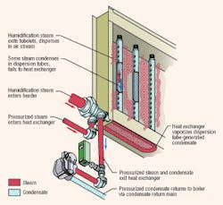
Reclaim tube-generated condensate. In nonpressurized steam applications, condensate should be routed via pipe from the dispersion assembly drain to the condensate return port in the steam generator. (Some dispersion tubes are installed with a pitch so condensate will flow back through the tube to the steam generator. Not all steam generators have a condensate-return port.) In classic steam-injection systems (with steam-jacketed dispersion tubes), dispersion-tube-generated condensate is revaporized by steam-jacket heat; therefore, all tube-generated condensate is reclaimed. However, if a short absorption-dispersion panel with pressurized steam is used, the most efficient way to reclaim condensate is to use a panel with a heat exchanger in the header to revaporize generated condensate (Figure 2).
SIDEBAR: Resources
Free white papers on heat gain and condensate management are available at www.dristeem.com/literature.
For steam-pressure-loss tables and more information on how to calculate loads, the free “Design Guide” also is available at the previously mentioned Website.
Further information on calculating loads can be found in “Humidity Control Design Guide” by Lew Harriman, Geoff Brundrett, and Reinhold Kittler, available through the American Society of Heating, Refrigerating and Air-Conditioning Engineers.
The director of marketing for Dri-Steem Corp., Bob Nelson has 28 years of HVAC experience, including 21 years specializing in humidification.
