Energy Impacts of Laboratory Ventilation Methods
Over lunch one day, a colleague asked whether rule-of-thumb methods used to determine laboratory directional airflow lead to excessive energy consumption. That led to an investigation into what drives the energy consumed by ventilation air. Our initial assumption was we must be wasting energy just using a rule of thumb of 10 percent offset of exhaust airflow over supply airflow. What we discovered surprised us.
Laboratory Ventilation Requirements
First, we looked at what is driving ventilation requirements. Laboratory and related spaces usually are required to have inward directional airflow to reduce the risk of the release of dangerous airborne agents—in particular, chemical, biological, and radiological materials. There are many standards that dictate directional airflow, including the U.S. Department of Health & Human Services’ Biosafety in Biomedical and Microbiological Laboratories; NFPA (National Fire Protection Association) 45, Standard on Fire Protection for Laboratories Using Chemicals; the U.S. Department of Agriculture’s (USDA’s) ARS Facilities Design Standards; the National Institutes of Health’s Design Requirements Manual; DOE (Department of Energy) Handbook 1132, Design Considerations; and DOE Handbook 1169, Nuclear Air Cleaning.
There is a clear consensus in design standards that laboratories should be at a negative pressure relative to adjacent spaces to induce airflow from clean, low-risk spaces to spaces with a higher risk of contamination. This negative pressure is generated by having more exhaust air than supply air in critical spaces.
A negative pressure difference can be achieved only when airflow overcomes resistance, such as that posed by small cracks. Open doorways create so little resistance a pressure gradient cannot exist. The airflows normally used in laboratory ventilation systems are too low to overcome air movements that occur in open doorways because of the fan effect of swinging doors, thermal gradients, and the wake of occupants passing through.
There are two common methods of determining how much airflow offset to allow in the design of a laboratory. One is to design a fixed percentage differential between total room exhaust and supply air. The other is to use a fixed offset per door as an estimate of the leakage paths between spaces. These two approaches arose from different concerns and have different implications. In this article, we will look primarily at the energy implications.
Fixed Percentage Offset
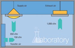
Percentage offset (Figure 1) addresses the concern that variability in supply and exhaust airflows could cause flow reversals. Older-style control systems have flow-rate oscillations on the order of ±5 percent. If space total exhaust is set at less than 10 percent above space total supply, exhaust can be expected on occasion to drop at the same time supply rises, with supply exceeding exhaust and resulting in a net outflow from a contaminated space. With a total offset of 15 percent, this situation can be avoided.
With percentage offset, transfer-air requirements are low for small rooms and high for large rooms. In practice, small rooms may be designed with larger offsets to ensure a target pressure drop across doors, while large rooms may have insufficient doors for the required offset and need special openings in walls to accommodate the additional flow.
In large rooms, a significant amount of air is required to maintain airflow rates. The higher the airflow rate, the greater the required offset airflow, which has to be made up from outside the space. In some cases, airflow rate can exceed normal closed-door leakage capabilities. Adjustable air-leakage paths, then, are added to the room to allow the closed-door room pressure to be adjusted.
Fixed Flow per Door
The flow-per-door concept arose from efforts to achieve a set differential pressure between clean and dirty spaces. Achieving this without creating transfer-air openings through walls requires a measure of the total crevice area between spaces. In a well-constructed building, major crevice areas are around door openings; the simplest approach, then, is to pick a fixed airflow per door. According to the USDA’s ARS Facilities Design Standards, “It is recommended that the infiltration of air into the containment area be at least 50 cfm per doorway at all times.”
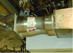
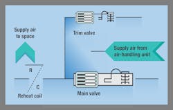
Designing on a flow-per-door basis produces arrangements similar to those for small rooms designed with flow offset. For large rooms with fewer doors per square foot, it can result in low offset requirements. Thus, control systems with the ability to reduce flow deviations from setpoint to a few percentage points, such as pneumatic bladder dampers with good linear control characteristics, are required. For very tight rooms, adding a smaller trim valve in parallel with the main control valve further improves flow-control precision (Figure 2).
Energy Consumption
Often, air cannot be recirculated in a laboratory, necessitating 100-percent-outdoor-air systems. To reduce the amount of energy needed to condition a building, the first order of business should be reducing the total amount of outdoor air required. For our study, six combinations of internal loading and exhaust requirements were used to determine the total outdoor-air requirement. These combinations were applied to five different room sizes. For each room, a 100-percent-outdoor-air system was assumed.
Supply air required for space conditioning was calculated based on two fixed internal-load densities: 15 W per square foot and 30 W per square foot. For each of the internal loads, exhaust rates of six air changes per hour (ACH), 10 ACH, and 15 ACH were applied.
Calculations for both fixed percentage offset and fixed flow per door, each with two levels of space thermal load and differing ventilation rates, were performed.
Calculations
Our study evaluated energy consumption driven by total outdoor air for a room under two scenarios. For each scenario, the outdoor-air total was taken to be the largest among the following:
- Required exhaust, calculated at 1 cfm per square foot.
- Supply air required for 15-W-per-square-foot cooling at a 15°F temperature difference.
- Actual exhaust equal to required exhaust-plus-transfer air with 15-percent, or 50-cfm, transfer-air offset.
- Actual supply, ensuring the cooling load drives the supply-air requirement.
Scenario 1 in the calculations is a fixed offset of 15 percent; Scenario 2 is a fixed flow per door of 50 cfm. For the 15-percent offset, a minimum of 50 cfm was required. A 50-cfm minimum is in accordance with the USDA’s ARS Facilities Design Standards and represents the smallest airflow difference that can be air-balanced.
Results
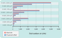
For a 15-W-per-square-foot fixed internal-load density, a difference between the two scenarios was seen only in the largest rooms (2,000 sq ft, 1,000 sq ft, and 500 sq ft) at 6 ACH. For these rooms, at a low air-change rate, more air is needed with the 15-percent offset, which indicates energy may be wasted with this design approach. For the rest of the rooms (100 sq ft at 6 ACH, 200 sq ft at 6 ACH, and all rooms at 10 ACH and 15 ACH), there was no difference (Figure 3).
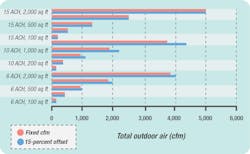
The results for a 30-W-per-square-foot fixed internal-load density were very similar to those for a 15-W-per-square-foot interior load. At 6 ACH and 10 ACH, the largest rooms require a higher quantity of outdoor air when designed with a 15-percent offset.
Figures 3 and 4 show little difference between the two scenarios. However, for large rooms with low air-change requirements, energy consumption likely will be less with a fixed airflow per door than with a fixed percentage offset. Additionally, figures 3 and 4 show the more significant driver of the amount of outdoor air required is room size and air-change rate.
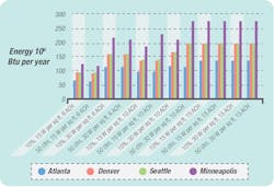
In addition to the quantity of outdoor air required, the energy consumed in the conditioning of air was considered. Atlanta, Denver, Seattle, and Minneapolis—four locations representing a variety of climatic conditions—were evaluated. Room characteristics and airflows were held constant. The results are summarized in Figure 5.
As can be seen in Figure 5, the location of a laboratory can have a much greater impact on ventilation-air energy consumption than design method (fixed vs. offset) can.
Conclusion
It is important to recognize that our study looked only at a simplified laboratory situation and that there are a number of practical issues that arise in actual design. Rooms with fume hoods or exhausted biological safety cabinets may require supply air beyond what is required for cooling the space load. Some laboratories with adjacent office space can use offset air drawn from the ventilation component of the office supply air without an additional energy cost being imposed on the building.
What our study revealed is that laboratory ventilation method—fixed percentage offset or fixed flow per door—has little effect on overall energy consumption compared with other design variables. Do the current rule-of-thumb methods used to size laboratory ventilation lead to unnecessary operational costs? The answer, we discovered, is no, not necessarily. A laboratory designer must consider a variety of conditions to determine the best approach. Overall energy consumption for ventilation air primarily is influenced by room size, required air-change rate, and location, not a design method of fixed flow or fixed offset.
Victoria Herman, PE, LEED AP BD+C, has extensive experience in building heating- and cooling-load calculation, duct sizing and design, and energy modeling for sustainable projects. Possessing broad knowledge of the LEED certification process, she has worked on more than 20 LEED projects and managed LEED coordination for several project teams. Kenneth Gow, PE, FPE, has more than 40 years of mechanical- and fire-protection-engineering experience, which includes systems for high-level biological laboratories, hospitals, commercial buildings, public buildings, schools, offices, high-rise buildings, nuclear containment laboratories, and industrial facilities. John B. (Joby) Evans Jr., PE, CAC, CxA, CBCP, CEM, LEED BD+C, has extensive experience in building commissioning and system design and coordination. He is proficient in commissioning high-containment facilities and analyzing energy consumption in commercial and industrial buildings.
Did you find this article useful? Send comments and suggestions to Executive Editor Scott Arnold at [email protected].


