How to Improve Airflow Analysis in HVAC Ducts
By SHEILA DUNN, Degree Controls Inc., Milford, NH
Indoor environmental conditions directly affect the health, comfort and productivity of a building’s occupants, equipment longevity and overall energy costs.
Accurate measurement of air velocity in HVAC ducts provides the information needed to examine and calculate the optimal airflow in HVAC systems. Larger HVAC ducts require a different set of tools than smaller diameter ducts.
When asked about where and how to take air velocity measurements in a duct, we can point to well-established standards and guidelines from the American Society of Heating, Refrigerating and Air-Conditioning Engineers (ASHRAE). Specifically, ANSI/ASHRAE Standard 41.2 prescribes methods for air velocity and airflow measurement, and ANSI/ASHRAE Standard 111 provides procedures for measurement, testing, adjusting, balancing, evaluating, and reporting the performance of building heating, ventilating, and air-conditioning systems in the field.
Where to Measure Airflow
Airflow can vary across the cross-sectional area of a duct. Measurement accuracy improves by taking measurements at multiple points and then calculating the mean. ASHRAE provides guidance on the number and location of measuring points within a plane for both rectangular and circular ducts. A minimum of 25 points is specified for rectangular or square ducts, and a minimum of 18 points is specified for circular ducts. Reference the instructions below to determine:
- Number of measuring points;
- Placement of measuring points.
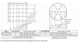
From ASHRAE Standard 111, Traversing a Rectangular Duct
The number of data points to be taken along each side of the duct depends on the width of that side of the duct. For duct sides less than 30 inches, five traversal points must be taken along that side. For duct sides of 30 to 36 inches, 6 points must be taken. For duct sides greater than 36 inches, 7 points are needed. Multiply the numbers provided in the table times the duct dimension to get insertion depth for the sensor probe.
From ASHRAE Standard 111, Traversing a Circular Duct
The preferred method is to drill three holes in the duct at 60° angles from each other, in order to cover all locations recommended using the log-linear method for circular ducts. Three traverses are taken across the duct, averaging the velocities obtained at each measuring point. Then the average velocity is multiplied by the duct area to get the flow rate.
Multi-Point In-Duct Measurements
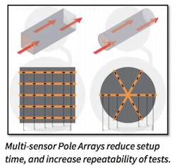
A Sensor Pole Array is optimal for in-duct HVAC airflow analysis. It is a linear array of airflow sensors assembled into a single tube element with USB outputs.
The Sensor Pole Array is designed for multipoint experimentation where there are predefined measurement locations, just as shown in the Log-Tchebycheff Rule (above) for calculating volumetric flow within ducts. With the Sensor Pole Array, air velocity, temperature, and humidity can be measured and recorded at multiple points in real-time for building duct performance testing.
Also, the Sensor Pole Array can be built to specified dimensions, including tube length, sensor quantity, pitch, and calibration range. Similarly, they reduce set-up time by eliminating complex fixturing that goes along with making multiple measurements across a plane, and Sensor Pole Arrays increase test repeatability.
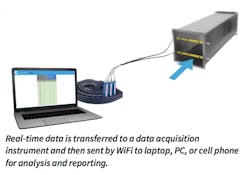
Very little impedance is imparted to the air-flow profile. The Sensor Pole Array can be used with data acquisition instruments to aggregate sensor data. The data acquisition instrument is paired with integrated software to collect real-time data on air velocity, air temperature, as well as humidity and altitude (or barometric pressure) for data logging and reporting.
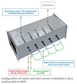
Embedded Air Velocity Sensors Provide Versatility
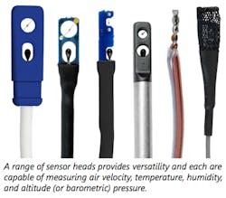
Embedded air velocity sensors provider users with a range of configuration options for the many diverse industry applications that exist. This includes velocity ranges, mechanical lengths, supply voltages, output communication types, as well as probe and remote head sensor styles.
The master sensor first records its own velocity reading and then averages all readings from sensors in the network. Next, the master sensor uses its 0-10V analog output to transmit the average velocity to the BMS or monitoring system.
All sensors are powered by universal 24VAC. Sensors are connected with a latching connector and 0.6 m [2 ft] of cable. The master sensor, itself, has 2 m [6.6 ft] flying leads to connect to the BMS system. The master sensor can communicate to as many as 15 slave sensors. This flexible solution ships as a kit, and master and slave sensors are already addressed.
Airflow Sensor as Key Element of HVAC Control System
A well-run HVAC control system is conducive to a healthy and comfortable indoor environment, helps maintain equipment life expectancy, and helps save costs. The control system is only as good as its sensing devices.
Therefore, care should be taken in choosing the right airflow sensor for your particular application. Close attention should be paid to both sensor mounting and location to ensure that it will function according to published specifications. With that in mind, here are some sensor considerations to evaluate:
The author is an Applications Engineer with Degree Controls Inc., and assists engineers and technical professionals in the development and support of airflow solutions for laboratory, building, and industrial safety applications. She has worked in the high-tech industry for 20+ years, holds a B.S. in Electrical Engineering from the University of New Hampshire, and is an inventor with several U.S. patents to her name. Contact her at [email protected].