Return Air Options for Floor by Floor Units
By KENNETH M. ELOVITZ, P.E., Esq.
Energy Economics, Inc.
Foxboro MA
Floor by floor units can be advantageous in multi-tenant buildings where tenants have different operating hours or the landlord wants to meter energy use by floor. Compared to central systems that serve multiple floors, ductwork tends to be smaller, so plenum height can be smaller. Smaller plenum height makes floor by floor units popular in places like Washington DC that have limits on building height. Squeezing eight inches out of each floor of a 20-story building could mean an additional story of rentable floor space within the allowable building height limit.
Floor by floor units range from five tons to 50 tons capacity and come in many configurations. They can be chilled or hot water air handling units, split systems (remote air-cooled condenser), or compressorized package units. Compressorized units can be water cooled or remote condenser (usually air-cooled). They can be cooling-only or heat pump. Any of these units can be constant volume, variable volume or VVT (variable temperature-variable volume).
Regardless of unit capacity or type, duct system design has to provide return air and outside air paths to the unit. If the unit has 100% outside air economizer for free cooling, the duct system design also has to provide for “spill” or relief of excess outside air introduced during economizer operation.
This article illustrates three ways engineers have managed return air, outside air, and spill for floor by floor units.
Conventional Ducting
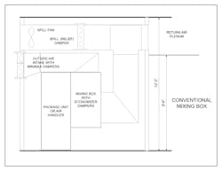
With conventional ducting, the unit has a mixing box and hard duct connections, as shown in Figure 1.
The mixing box has outside and return air dampers to control outside air flow into the unit. If the system has 100% outside air economizer for free cooling, exhaust fans controlled to maintain building pressure are often used to relieve or “spill” extra outside air.
Figure 1 shows that the outside air and return air ductwork connections to the unit make the mechanical room congested. In addition, not all manufacturers offer an accessory mixing box for this type of unit. In that case, the mixing box and its dampers would be field fabricated.
Return Air Room
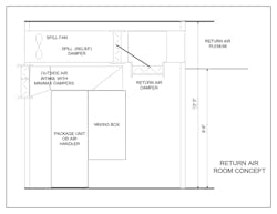
Making the mechanical room a return air room reduces congestion and can reduce first cost because it saves ductwork. Figure 2 shows this arrangement. The unit still has an outside air duct, but the return duct is eliminated because return air flows through the mechanical room into the mixing box.
Here is how the Return Air Room concept works: Return air from the conditioned space enters the ceiling plenum or return duct and flows across the ceiling back to the mechanical room. The supply fan in the unit draws free return air from the mechanical room. The resulting negative pressure in the mechanical room draws the return air into the mechanical room. A ceiling return plenum functions as a huge duct, so the pressure drop through it is very small - probably less than 0.10-in wg. If the return is ducted, a return fan might be needed to overcome the pressure drop through the return duct.
If the unit has an outside air economizer, the system needs dampers and controls to reduce the return air quantity for every cubic foot of outside air introduced for free cooling. A damper in the wall of the mechanical room above the level of the ceiling of the occupied space can throttle return airflow, but the outside air introduced for free cooling would pressurize the occupied space. As with any system that has an outside air economizer, the return air room needs a way to relieve or “spill” the extra outside air.
An exhaust fan in the outside wall above the ceiling of the occupied space would work, but it would be convenient to have that exhaust fan in the mechanical room for service access and noise control. One solution is to run a relief/exhaust duct sized for the return/spill air flow across the mechanical room ceiling. The duct connects the plenum above the ceiling of the occupied space to an exhaust louver in the outside wall. The duct needs an opening to the mixing room (with a damper) to let return air into the mechanical room, a damper at the connection to the outside wall to control spill air flow, and a fan. Figure 2 shows these components.
As the outside air damper opens for economizer free cooling, the return air damper closes, and the spill damper in the duct opens. The excess outside air escapes outdoors through the duct and louver. The spill fan comes on if needed when the outside air quantity is too high for gravity relief to keep the floor pressure within the desired range (usually 0.02-in wg to 0.05-in wg).
Mixing Room
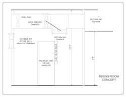
The mixing room concept eliminates both the return air and outside air duct connections to the unit. Figure 3 illustrates this concept. Because the mechanical room is under negative pressure (created by the fan in the unit), outside air also enters the room (through a damper) where it mixes with return air before it enters the unit. The mixed air enters the unit and gets conditioned; the supply fan pushes the air out through the supply duct and into the space.
With the Mixing Room Concept, the entire room will be at mixed-air temperature, well above room temperature in summer and well below in winter during economizer operation. Therefore, partitions to occupied space need to be insulated.
In a cold climate with a high percentage of outside air, a unit heater in the mechanical room can provide freeze protection and even substitute for a preheat coil in the unit. Remember that the unit heater setpoint will be mixed-air temperature (typically 50F to 60F), not normal room temperature.
Other Considerations
(1) With either the Return Air Room or the Mixing Room Concept, the mechanical room becomes part of the HVAC system. The walls need a non-combustible or limited combustible finish such as drywall. Seams need to be taped to make the room reasonably air tight, but sanding smooth for finish quality painting is not necessary.
(2) The owner must be diligent about not using the room for storage. The HVAC system will distribute any odors or smoke released in the room to the entire occupied space. In exchange for those restrictions, the mechanical room can be smaller than it would otherwise be.
(3) Control is the same as any other outside air economizer with an exhaust fan (not a return fan). Controlling the return air damper to maintain a constant negative pressure in the mixing room is easy to implement. With min/max outside air dampers, the minimum outside air damper section opens whenever the unit runs. With a constant negative pressure in the mixing room, the pressure drop and therefore the airflow across the open minimum outside air damper is constant, regardless of supply fan flow. An independent control loop controls the spill fan (variable speed or discharge damper) to maintain constant pressure on the floor (or in the ceiling return air plenum) as the max outside air damper opens to admit more outside air for the economizer cycle.
The Return Air Room and Mixing Room concepts are a bit unconventional because they make the mechanical room itself part of the HVAC system. They have been applied successfully many times. By eliminating large ducts in what is usually a tight space, these concepts can reduce first cost without compromising performance.
A longtime member of HPAC Engineering’s Editorial Advisory board, the author is an engineer (mechanical and electrical) and in-house counsel for Energy Economics, Inc., a consulting engineering firm in Foxboro, MA. He is also an Adjunct Teaching Professor in the Architectural Engineering program at Worcester Polytechnic Institute.


