NEMA Standards Are Giving Motor Bearings the Shaft
Whether used to control the speed or the torque of an alternating-current motor, a variable-frequency drive (VFD), also known as an adjustable-speed drive or inverter, can induce unwanted voltages and currents on the motor’s shaft, destroying the motor’s bearings (to learn more, read the author’s May 2010 HPAC Engineering article, “Extending Motor Life With Sustainable Shaft Grounding”). The repair or replacement of failed motor bearings can wipe out the savings a VFD yields and severely diminish the reliability of an entire system.
While “inverter-duty” and “inverter-ready” motors have insulation to protect the windings, the bearings—their most vulnerable parts—often are ignored. Unfortunately, many buyers of these motors do not understand this.
Although current National Electrical Manufacturers Association (NEMA) standards highlight the possible need for extra bearing protection for inverter-driven motors, the language often is not specific enough to guide motor manufacturers and has not been updated to include new research results and technology developments. Stronger, reworked standards calling for effective mitigation would go a long way toward educating motor users and clearing up common misconceptions.
The Need for Updated Standards
In its key role of information provider, NEMA is in the unique position to update its MG 1 standard, Motors and Generators, to more clearly state that common-mode shaft voltages are present in virtually all motors fed by pulse-width-modulated VFDs.
NEMA’s current standards say motors controlled by VFDs containing insulated-gate bipolar transistors should be designed to withstand repeated spikes of up to 3.1 times the motor’s rated voltage at rise times not less than 0.1 microsecond. Yet, when addressing the potential for bearing currents, the language is far less prescriptive.
NEMA MG 1-2009 (Revision 1-2010) correctly states, “Shaft voltages can result in the flow of destructive currents through motor bearings, manifesting themselves through pitting of the bearings, scoring of the shaft, and eventual bearing failure.” It recommends bearing insulation at one end of larger motors (defined as “usually 500 frame or larger,” horsepower unspecified), if the peak shaft voltage is greater than 300 millivolts. Unfortunately, the paragraph dealing with these larger motors only mentions circulating end-to-end shaft currents caused by magnetic dissymmetries under sinusoidal operation. It fails to add that the bearings of large motors also can be plagued by VFD-induced high-frequency, capacitively coupled common-mode voltages.
In a paragraph on “much smaller motors” (frame size and horsepower unspecified), the standard recommends insulating both bearings or installing shaft-grounding brushes to divert currents around the bearings. For these motors, the standard correctly explains, a VFD can generate high-frequency common-mode voltage, which shifts the three-phase-winding neutral potentials significantly from ground. Because the voltage oscillates at high frequency and is capacitively coupled to the rotor, the current path to ground can run through one bearing or both. The standard neglects to mention that high-frequency circulating currents also may be present in inverter-driven motors as small as 100 hp.
To summarize, NEMA MG 1 omits common-mode voltages from its paragraph on larger motors and omits circulating currents from its paragraph on smaller motors. Another problem is that neither a grounding brush nor insulation is a reliable, long-term solution to the problem of electrical bearing damage at the system level.
To its credit, NEMA MG 1 does correctly point out that, “Insulating the motor bearings will not prevent the damage of other shaft connected equipment.” When the path to bearings is blocked by insulation, current will seek another path (e.g., through a pump, gearbox, tachometer, encoder) to ground.
Best Practices for Mitigating Bearing Damage
Manufacturers and users of inverter-ready motors should strive to protect the motors’ bearings as well as their windings. The following measures have proven effective under actual operating conditions and should be considered for inclusion in any NEMA standards updates:
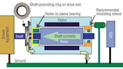
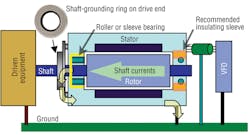
• For motors above 100 hp, in which both circulating currents and common-mode voltages can cause bearing damage, an insulated bearing on one end and a shaft-grounding ring on the other (Figure 1) provides the best protection from electrical bearing damage.
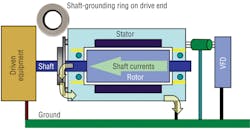
• For motors 100 hp and less, adding a shaft-grounding ring either inside of a motor or externally (Figure 2) effectively protects bearings and attached equipment from currents.
Conclusion
Virtually all inverter-driven motors are susceptible to bearing damage, but for too long, the importance of shaft grounding to protect motor bearings has been ignored or underestimated.
Current NEMA standards dealing with the problem of shaft voltages are incomplete or not specific enough to help. They do not acknowledge the combination of capacitively induced shaft voltages and high-frequency circulating currents from VFDs. Furthermore, they fail to take into account recent advances in technology.
While some motor manufacturers provide bearing protection in selected models, most motors labeled “inverter-duty” or “inverter-ready” are not adequately protected. It is incumbent, then, on specifiers to make sure any motor to be used with a VFD truly is inverter-ready.
Did you find this article useful? Send comments and suggestions to Executive Editor Scott Arnold at [email protected].


