Considerations for Selecting Pumps and Fans
The loads are calculated and fan CFM or pump GPM are known. Ducts and pipes are laid out and pressure drops calculated, too. So it is time to select fans and pumps. Manufacturer selection programs are great tools and time savers, but engineers have several factors to consider before choosing the first item that comes up in the list of models that meet the specified flow and pressure levels:
1) Plot the design operating point on the pump or fan curve and determine whether the design operating point is on the steep or flat part of the curve. Evaluate the effect of a small change in pressure due to field conditions or calculation uncertainty on the resulting flow.
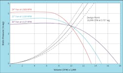
Figure 1 shows three fan selections for the same duty: 10,000 CFM @3.75” wg. Suppose field conditions like unplanned offsets or mitred elbows, instead of the long radius elbows used for design, mean the system would need 4.25” wg (short dashed system curve) instead of 3.75” wg (solid system curve) to push 10,000 CFM through the duct. Without a fan speed change, the 24” fan (steeper curve/pink line), would back up on its curve and deliver 9700 CFM.
By comparison, the design operating point is on the flat part of the 30” fan curve, so that fan would deliver only 9500 CFM. If delivering design CFM is important, the 24” fan might be a better choice than the 30” fan, even if it were not smaller and less expensive. While the airflow differences in this example are small, other cases might make a bigger difference, so the principle is important to keep in mind.
On the other hand, operating a pump near the flat part of its curve can be an advantage in a variable flow system. On the steep part of the curve, small changes in flow as valves close means larger changes in pressure. That increase in pressure difference can push more flow through control valves, affecting temperature control. Too much pressure increase can even force zone valves off their seats, creating noise (valve chatter or whistling, as water speeds through small openings) or overheating/over cooling the space served. On the flat part of the pump curve, pressure remains relatively constant, so individual control valves can vary flow more consistently over a wider range of overall system load.
On the other hand, a differential pressure bypass valve limits the pressure differential available to the system. Even if the design operating point is on the steep part of the pump curve, the system sees a relatively flat pump curve at flows less than design.
Especially for fans (forward curve more than airfoil or backward inclined), the flat part of the curve ends in the region of instability. A design system curve that meets the fan curve close to the peak efficiency point risks moving into the region of unstable operation if field conditions (or a calculation error) make the actual system curve steeper than the design. That risk is one of the dangers of over sizing fans.1
There is no one answer to whether to select for the “steep” or the “flat” part of fan and pump curves. The choice is a question of engineering judgment, considering the many factors that affect overall system design;
2) Avoid picking the largest or smallest impeller in a pump. Leave room to trim or replace the impeller to overcome field conditions or accommodate changed conditions.
Likewise, leave room for possible fan speed increases to overcome field conditions. The 24” fan selection in Figure 1 (1569 RPM) is near the catalog maximum allowed speed of 1588 RPM for that fan. It might not be possible to speed up that fan to achieve the design 10,000 CFM.
If the design fan speed is close to the maximum speed for Class I construction, then specify Class II construction. The small cost increase for the next higher construction class pales next to the possibility of having to replace a fan (or speeding it up without checking construction class limits and letting the blades fly apart). Check the specified construction class on the submittals in case a contractor or manufacturer’s rep who does not know all the job considerations submits the lower class construction on the basis that it is “good enough” to do the job. Remember that once the job has been specified and bid, the obligation is to furnish equipment as specified, not as what could have been specified;
3) Check the fan noise rating for the operating point under consideration. The next larger or next smaller fan might be much quieter. Balance efficiency, noise, and operating point when making fan selections;
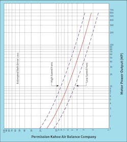
4) When selecting motors, add belt and drive losses to the fan brake horsepower to determine the load on the motor. Belt and drive losses vary with fan speed and load, but 5% of fan brake horsepower is a good average to use for design.2 On both pumps and fans, consider the need for non-overloading operation. HP increases as CFM (or GPM) increases at lower pressure. The increase is much greater on forward curved fans than on backward curved or airfoil fans and pumps. Use your engineering judgment to decide whether operating a motor within its service factor might be okay for the rare case when the pump or fan might run at high flow/low pressure/increased horsepower.
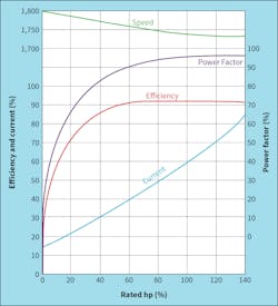
Balance the cost of the next larger motor (with potential wiring and starter changes) against ways to reduce system resistance so the smaller motor can operate within its capacity. Oversized, lightly loaded motors add unnecessary first cost. They are also inefficient and run at low power factor. At the same time, Figure 2 (Bell and Hester, Electric Motors, HPAC, December 1981, p. 51) shows that motor efficiency is relatively constant at loads of 65% of nameplate or more. Providing the next larger motor for non-overloading operation or safety factor to accommodate field changes or future expansion does not necessarily increase operating cost;
5) Favor nominal 1800 RPM motors over 3600 or 1200 RPM motors. 1800 RPM motors are standard and readily available at supply houses. 3600 and 1200 RPM motors might be special order items, extending outage time in case of motor failure. For the same duty, 3600 RPM pumps and motors make more noise than their 1800 RPM counterparts. Pump noise can be important, especially for smaller pumps that might be located near occupied space;
6) When selecting fans, consider differences in start up and operating temperatures. Cold air is more dense (greater mass flow), so it requires more HP than warm air. Hot air (for instance, kitchen exhaust), requires provisions like heat slingers to protect bearings from heat. Likewise, select fan type to keep motors out of hot airstreams;
7) Inline pumps can save space, but consider motor size and service needs like having to remove a motor to service or replace bearings or the motor itself. A mechanic can probably handle motors up to 3 HP (about 75 pounds), though maybe not if the pump is up in the air and the mechanic is on a ladder. A 10 HP (130 pounds) or 15 HP (235 pounds) motor almost certainly will require rigging a chain fall, and maybe a helper;
8) Consider discharge velocity and projection requirements for exhaust fans. For example, a 1200 CFM exhaust might use a 12” duct to provide adequate conveying velocity (1500 ft/min) without excessive pressure drop (0.25”/100 ft). But a discharge velocity of 2500 ft/min might be desirable for plume rise and dilution. If adding a discharge cone to increase velocity, the change in velocity pressure from 0.14” wg (1500 ft/min duct velocity) to 0.39” wg (2500 ft/min) is 0.25” wg of energy input to be added when specifying fan TSP.
Flow (CFM or GPM) and head (in. wg total static pressure or feet of water) are the key performance factors for selecting fans and pumps. However, engineers have other choices and considerations to weigh when choosing a specific make and model as the basis of design.
A member of HPAC Engineering’s editorial advisory board, the author is both a mechanical and electrical engineer, as well as in-house counsel for Energy Economics, Inc., a consulting firm based near Boston MA. Email him at [email protected].
REFERENCES
1. For an example of this problem (as well as other engineering case studies), see Elovitz, Tales from an Engineering Career, page 319;
2. Associated Air Balance Council, National Standards, 1982, p. A.62.
About the Author
Ken Elovitz, P.E., Esq.
A longtime member of HPAC Engineering's Editorial Advisory Board, Kenneth M. Elovitz, P.E., Esq., is an engineer (mechanical and electrical) and in-house counsel for Energy Economics, Inc., a consulting engineering firm in Foxboro, MA. He can be reached at [email protected].


