Naturally Ventilating Equipment Rooms: A Guide
By GEORGE GAMES, P.E., North East HVAC Engineering & Consulting, East Brunswick, NJ
Recently, I reviewed design drawings for an enclosure housing industrial electrical equipment. The equipment consisted of 5kV cabinets and switches along with some step-down transformers. The design intended that the equipment be cooled via a natural ventilation configuration consisting of two intake “supply” louvers located low on a double door at one end of the enclosure and two “exhaust” louvers located at the far end of the enclosure, but located higher than the intake louvers (see Fig. 1 for a simplified diagram of the enclosure).
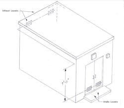
All louvers were sized at 18 in. wide by 12 in. high. No bird or insect screens were specified.
The heat load of the equipment wasn’t listed, but I suspected this configuration wouldn’t work well enough to keep the equipment sufficiently cool. Forced ventilation was probably going to be needed.
Let’s investigate the effectiveness of natural ventilation for an application such as this and see what we need to consider.
ANALYSIS
For a situation such as this, you need to consider three items:
1. The amount of cfm of ambient air needed to keep the indoor space at the temperature you select, or at the maximum operating temperature rating of the equipment;
2. The pressure developed in a thermal gravity effect configuration using the temperature (and corresponding air density) selected of the indoor enclosure; a thermal gravity effect calculation is used for this;
3. Determine if the amount of airflow calculated in step one will travel through the openings in the enclosure, based on the restriction of those openings versus the pressure developed by the thermal gravity effect.
For natural ventilation to properly work, it is always advantageous to have a significant elevation difference between the source of air into a building (or structure) and the exhaust outlet(s). The greater this difference, the greater the motive force (buoyancy in this case) that moves the air thru the building.
In this case, the heat given off by the equipment heats the air and provides the buoyancy to the air to move it up and out through an opening located up high. This movement would pull cooler air in through an opening located elsewhere at a lower elevation. The amount of airflow is a function of the heat input, the relative densities of the air outside and inside, and the restriction placed on it by the configuration of the openings.
For instance, regarding the restrictions, louvers with a 54% free area and a bird screen would impart less restriction to airflow than louvers with a 54% free area and an insect screen, or louvers with a 45% free area and a bird screen. By the way, insect screens that have a tighter mesh increase resistance substantially, and get dirtier quicker… which further increases resistance. The less resistance at the louver’s openings, the more airflow passes through.
The “duct system” in this type of situation becomes the enclosure with the openings at either end. In other words the duct system here is a box with two openings. The enclosure (the box) acts like the duct, and the openings become the ends of the “duct” where in which the airflow passes. Because the enclosure is large relative to the size of the openings, airflow is slowed down substantially (even with equipment inside) and the losses attributed to the enclosure are essentially non-existent, or of little consequence. In this case, then the “system’s” losses are attributed to the restriction the openings impart to the system….i.e., the restriction to movement of air in and out through the louvers.
Let’s start the analysis by making some assumptions and design decisions:
Assumptions:
1. The heat given off by the equipment is 3,750 Btu/hr (mostly from the transformers);
2. An enclosure located at Newark Liberty International Airport, in northern New Jersey.
Design Decisions:
1. Select an indoor enclosure temperature (to maintain) of 100 F. Typically industrial electrical equipment can operate safely at 104 F; so we are in good territory here at 100 degrees;
2. Select an outdoor ambient temperature of 94.3 F DB / 74.4 F MCWB (Newark Airport’s 0.4% cooling dry bulb; Chapter 14, Climate Data, Ref. 1). This is the most conservative selection…. any outdoor temperature selected less than this will be of benefit, with regard to less CFM required;
3. Difference in height of the intake and exhaust louvers (based on the horizontal centerline of the louvers) = 7 feet;
4. Use of Ruskin louver model ELF375DX, a 4 inch deep louver with 37.5 deg angle drainable stationary blades, rated at 54% free area.
COOLING AIRFLOW REQUIRED
Let’s now calculate the amount of airflow required to keep the enclosure interior at 100 F.
To do this, we use the familiar sensible heat equation Q = cfm x 1.08 x dT, (Ref. 1: Chapter 16, Eq. 33), where:
Q = 3,750 Btu/hr;
dT = (Tenclosure – Tambient ) = 100 – 94.3 = 5.7 F;
solving for airflow (cfm)….cfm = Q ÷ (1.08 x dT) = 3,750 ÷ (1.08 x 5.7) = 609 cfm; let’s round up to 610.
Thus, the calculation determines that you will need 610 cfm of the cooler outdoor air to flow through the enclosure to keep the inside at your “design condition” of 100 F. (See Note 1 below for further clarification on the use of this equation.)
Analytically speaking, what we need to do from this point on is …..to ensure the airflow will be allowed to flow through the enclosure unimpeded by the enclosure’s duct system – our “box with two openings”. In essence the inlet and outlet openings, located where they are, need to be large enough to impart no more static pressure than the pressure calculated by the thermal gravity effect equation.
THERMAL GRAVITY EFFECT
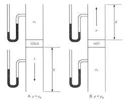
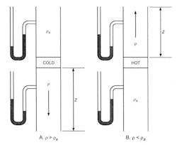
Now, let’s determine the pressure developed by the thermal gravity effect due to the physical configuration and the heat developed in the enclosure. To do this we will need to use Equation 14 in Chapter 21 of Ref. 1. See Fig. 2, Diagram B, for a schematic of the scenario representing our configuration (Ref. 1, Chapter 21).
The equation is: ∆Pse = 0.192 x (pa - p) x (z2 - z1), where the variables are defined as:
∆Pse = thermal gravity effect, inches of water gage (inWg);
pa = density of the ambient air, lbm/cubic ft;
p = density of the air inside the enclosure, lbm/cubic ft;
z2 = elevation of the exhaust louver, ft;
z1 = datum; elevation of the inlet louver, ft;
0.192 = conversion factor resulting in a final value of inches of water gauge.
Substituting known values into the variables we have:
pa = the density of ambient air, at the 0.4% DB condition we selected, is = 0.0700 lbm/cubic ft (derived from a specific volume of approx. 14.28 cubic ft/lbda; as read from the psychrometric chart in Chapter 1 of Ref. 1);
p = 0.0693 lbm/cubic ft (derived from a process line travelling horizontally to the right - without a change in moisture - starting at the density at pa, across and over to 100 F), arriving at approximately a specific volume of 14.42 cubic feet/lbda;
z2 - z1 = the elevation difference, is = 7 ft;
Solving for the pressure developed by the thermal gravity effect, we have:
∆Pse = 0.192 x (0.0700 – 0.0693) x 7 = 0.0009 inches Wg, or rounding up, 0.001 inWg.
The result tells us that the difference in densities of the air outside, and the slightly heated air inside the enclosure, only results in a pressure differential between the outside and inside of one-thousandth of an inch of water. This is hardly a pressure differential that will result in air movement in and out of the enclosure.
LOUVER RESISTANCES
So how much pressure is required to move 610 cfm through the louvers? Or, said another way, how much pressure (resistance) do the louvers impart on the airflow required? Let’s first calculate the velocity of the air through the 18” x 12” louvers. At this size, the louvers have 0.54 square feet of free area (36% free area; see Note 2 below). It is expected that each louver will pass 305 cfm of airflow. Finding the free area velocity at each louver gives us 305/0.54 = 565 fpm.
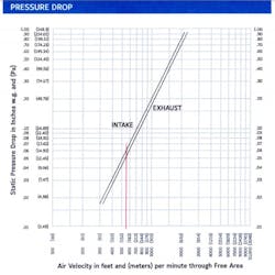
Looking now at Fig. 3, a copy of the pressure loss chart for the louver specified, we see that at approximately 565 fpm, the pressure developed (or needed to push or pull through 610 cfm) is approximately 0.06 inWg on intake flow, and about 0.053 inWg on exhaust flow. Therefore, a total of 0.113 inWg of pressure is required to move 610 cfm through the enclosure. Recall, we’re neglecting the pressure losses inside the enclosure with this analysis only to simplify the problem (See Note 5 for further clarification).
Comparing this to the pressure developed by the thermal gravity effect, one sees that relying only on the heat source inside, to heat the air up to create the buoyancy needed to move the air through the enclosure, the thermal effect alone will not develop the pressure needed to move the airflow (through the louvers) as required to cool the enclosure.
Thus, this design as configured will hardly cool the interior as intended and will require forced mechanical ventilation to cool it as necessary.
Note, that the analysis doesn’t include bird or insect screens covering the louvers. Including them would increase the resistance even more so, and the pressure needed to move the airflow through.
ADJUSTMENTS TO THE NATURALLY VENTILATED SOLUTION
To overcome the problems we’ve encountered with this ventilation method, we could do a few things, though there aren’t many.
• We could increase the height differential of the inlet and exhaust openings. Just to illustrate how elevation affects this phenomena……an elevation differential of 1000 feet gives us only 0.134 inches of Wg. However, this is hardly a practical solution in this case;
• We could enlarge the louver sizes to reduce pressure losses;
• We could relocate as much of the equipment outdoors if possible, to reduce the internal heat load;
• We could use a combination of all three items above.
As we can see, this method has its drawbacks.
FORCED MECHANICAL COOLING SOLUTION
As an alternative to natural ventilation, using an exhaust fan involves the following:
You will not need to ventilate the enclosure during the winter, therefore the intake louvers would need to have dampers installed to keep infiltrated winter air out; you do not want the enclosure’s heater(s) to run continuously. Good quality sealing dampers need to be selected; two position (open or closed) dampers are adequate here, no modulation is needed. The louvers should have at least a bird screen mounted on the outside of the louver. If insects are prevalent in the area, then an insect screen is advisable. Also, pulling in air without filtration into an electrical equipment room is not advisable. Air is dirty and will quickly dirty the enclosure and equipment, and possibly endanger it over the long haul.
Assuming the same airflow requirement, an exhaust fan would need to be selected to overcome all the pressure requirements of the equipment at the intake louver. Excluding filtration, the pressure requirements would include the bird or insect screen, the louver and the damper losses (See Note 4 below for guidance). The losses for these three components in series would be summed up. These losses would be considered the fan’s external static pressure (ESP) requirements.
Assuming the exhaust fan selected will be installed in a factory provided sleeve, with protective OSHA screen, a motorized damper, and exterior louver, then the pressure losses of these factory installed items would be considered (by the fan manufacturer’s rep) an integral part of the fan assembly’s pressure requirement, and what you calculated would be the “external” portion of it. In all cases the design engineer ought to confirm this to ensure those fan housing item losses are accounted for. Giving the fan manufacturer’s rep the ESP requirements [and the temperature of the ventilation air of 100 deg F] would be sufficient for them to select a fan with a total pressure rating to overcome these losses and provide the 610 cfm needed. See Note 3 below for further information on system air temperatures.
If you decide to include filtration then the losses for the filters would need to be added to the ESP value. The rated losses of the filters when dirty is best to include here. Also, any ductwork used in this intake system configuration, and its losses if not insignificant, should be included in the ESP estimate.
Now of course, as you can see, the forced mechanical ventilation solution gets complicated. Dampers either need to be manually opened or closed at the right time of season, or need to be motorized and automatically controlled via a thermostat. In the latter case, electric power feeds need to be routed to the dampers and control wiring back to a control panel or thermostat. The heaters (needed during the winter) would need to be interlocked with the exhaust fan to ensure one or the other only operates at one time. If the enclosure is located in a remote area, then remote annunciation may be needed to alert personnel to a system problem.
The forced mechanical solution guarantees cooling airflow, however, it comes at the expense of more equipment, maintenance and cost. Keeping the equipment clean with regular cleaning of the screens, louvers and dampers is important to keep the system operating as close to its design condition as much as possible so that the required airflow is maintained.
As a precaution, whether naturally ventilating or using forced ventilation, always ensure the heat load given off by the equipment is estimated or calculated correctly. You don’t want to use a value that (for the sake of expediency) was overestimated, as that will only increase your airflow requirements unnecessarily.
##########
NOTES:
1. In the interest of quickly illustrating the use of the heat transfer equation, I employed, the equation considered the density of air at 0.075 lb/cubic feet, resulting in a constant C value of 1.08. In our case the incoming air is hotter and its density less (at 0.070), resulting in a C valued at 1.008 (or 1.01). This would result in an airflow correction to 653 cfm, and this would be the correct cooling cfm required. The correct density of the incoming ventilation air is important to consider - see Ref. 2 for further discussion on manipulating the constant C as situations differ.
2. The free area ratings of louvers are usually established at a louver size of 48” x 48”. Any louver size smaller or larger will have a free area that is correspondingly smaller or larger.
3. Correctly done, the ESP would first be summed based on available equipment loss charts (that are based on standard air at 70 deg F), then corrected for the operating temperature of the system, then given to the fan representative for fan selection. The ESP of a system changes as temperature (and density) of the air changes. Fans will expend more Hp energy on systems operating with colder air as opposed to warmer air, thus temperature corrections are important.
4. SMACNA’s “HVAC Duct System Design” handbook has pressure loss charts for bird and insect screens, louvers and dampers, and other system components. However, for louvers and dampers being used, you’re better served by using loss charts from the manufacturer’s data.
5. Airflow moving thru a space doesn’t contribute any pressure losses (worth considering) because the cross-sectional size of the space is huge when compared to a duct’s cross-sectional size. However, as the size of the space gets smaller AND the equipment inside occupies more of the volume of the space, then some contemplation of the losses would need to be considered, especially as velocity of the airflow increases.
REFERENCES:
1. ASHRAE Handbook, Fundamentals – 2017 Edition
2. HPAC Engineering, Sept. 2020 Issue, 'The Heat Transfer Equation’s Factor C, ‘Explained’ '
CONTACT:
Email the author at: [email protected].