Pro Tip: Check Ductwork System Pressure vs. Air Handler Specs
By GEORGE GAMES, P.E., North East HVAC Engineering & Consulting, East Brunswick, NJ
This past spring, I published an article here entitled, Screen Cleaning: Best Not Overlook Those Seemingly Minor Details. This article talks about another detail that can also be overlooked in HVAC systems: ductwork design. It can have adverse effects on the equipment you may be specifying.
Late last year, my mom was in the hospital. While visiting with her and staying for extended periods, I would wander over to the room’s window to take a look outside. The view overlooked lower rooftops of other adjacent hospital buildings; rooftops housing much HVAC equipment. I found something very interesting and thought-provoking regarding a large air-handler just below the window.
- NOTE: These personal photos include a slight reflection of the louvered opening of a terminal wall unit inside the room from which the pictures were taken. (Yes, it’s annoying, but I couldn’t eliminate it. My apologies.)
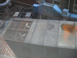
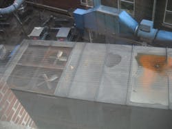
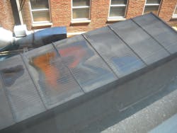
Above, we see a picture of a rooftop air-handler with a deep indentation in its top surface. The indentation was deep enough that water is seen puddled and discolored from being stagnant. Although I cannot guess correctly at the actual reason for the indentation, I started thinking that it could have been an issue with system pressure that was underestimated or overlooked. Or it simply could have been something heavy that may have fallen in that spot. For the sake of some engineering analysis and hopefully some enlightenment, let's assume that system pressure was the cause, and investigate this possibility further. It turns out to be a design matter that is quite important to contemplate – not a minor detail in the least.
Looking at the photo, it appears that the roof indentation occurs on the negative pressure side of the air-handler. Let’s analyze further and confirm.
On the left end of the air-handler is the condenser section with fans. The unit is operating; one can see two stationary fans and two that are spinning. Just to the right of them is the return/mixed air box; you can see (not very clearly) an OA or EA louver opening on the near side wall panel. It’s likely an EA opening as there is no hood protecting an OA opening, which is typical. But let’s assume it’s an OA opening for the sake of this discussion. Moving further to the right is the section with the indentation; and, below, further to the right, is the coil section where you can see the cooling coil’s white PVC condensate drain P-trap and piping coming out of the casing on the near side wall.
Prior to this coil section is the filter bank (or banks). Continuing on past the coils, is a large section that is as expected …..the supply air side on the right end of the machine with the supply fan (or fans) located within. Although I did not take a photo showing the SA duct exiting the right end of the machine, it was a horizontal discharge configuration, as opposed to bottom discharge. The SA duct ran out along the roof and disappeared downward into the roof surface further on to the right.
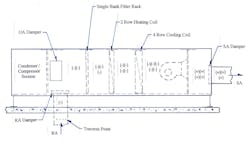
Thus, we have a draw-through air handler here and based on where the indentation is relative to the cooling coil’s condensate drain piping, we can safely assume the indentation occurs upstream of the cooling coils and is located in the negative air pressure region of the machine. (see Fig. 1 for a diagram of a draw through unit simulating the particular setup here, and Note 1 at the end of the article).
What Can We Make of This?
On these large air distribution systems, often the total ductwork external static pressure (ESP) can reach 6 to 7 or more inches of water gauge (inWg) - ie., return and supply air sides combined. This amount of static pressure can occur in a hospital application where many duct branches are likely to be needed, as well as smaller ductwork sizes to fit in confined overhead spaces, and ductwork equipment and components mounted within the ductwork; all concerns that contribute to a duct system’s static pressure buildup. Also, over time, modifications to the ductwork system [needed for internal space renovations] can add more pressure (negative and/or positive) to the duct system if not carefully accounted for, or done without regard to the air handler’s airflow capacity and static pressure capabilities.
So, let's see how system pressure can become a problem here. But first, let’s assume and establish some starting design parameters for the air-handler.
Air-handler casing pressure limit = +/- 8 inWg (based on Trane’s Climate Changer CSAA model). Note: this is not a black and white limit but is a pressure at which deflection in the machine’s panels will start to occur.
- Single SA fan, supply airflow 30,000 cfm, draw through configuration, horizontal discharge;
- Dual row heating coil, 8 fins per inch (fpi);
- Four row cooling coil, 8 fins per inch (fpi);
- We’ll assume the opening in the photo is an OA opening, then;
- OA airflow damper size = 2.5 ft wide x 5 ft high (opposed blade movement with crimped leaf edge blades);
- OA Airflow (cfm) = 10% of SA = 3,000 cfm;
- OA damper blades positioned at 20 degrees away from the duct centerline, approaching closed position - See Note 2 below;
- No economizer option; max OA = 3000 cfm;
- Return Airflow (cfm) = 27,000 CFM; bottom inlet;
- RA damper size at bottom of air handler = 2 ft x 5 ft (10 sq ft overall, opposed blade movement with crimped leaf edge blades);
- RA damper “free” area when fully open = 90% of damper size;
- RA velocity across RA damper = 3000 fpm “free air” velocity (based on 9 sq ft of unobstructed opening in damper, blades fully open);
- RA damper loss coefficient C: C = 0.52 (See Fig. 2; Ref. 1, Fitting #CR9-4 – for blades fully open; ie., with theta Θ = 0 degrees);
- OA damper loss coefficient C: C = 3.16 (See Fig. 2; Ref. 1, Fitting #CR9-4 – with theta Θ = 20 degrees away from centerline, towards closed position, and L/R = 1.5);
- One filter bank/rack (no pre-filter bank here to simplify the discussion; but usually present in these large AHUs);
- Filter pressure drop (clean) = 0.30 inWg (2 inch deep MERV 11; Ref. 3);
- Filter pressure drop (dirty) = 1.00 inWg;
- Design air velocity across coil surfaces = 600 fpm (target velocity is usually 500 to 600 fpm max; Ref. 4, Table 9-8);
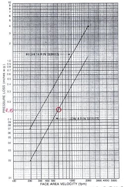
- Row 8 fpi Heating Coil pressure drop = 0.15 inWg (See Fig. 3; Ref. 4);
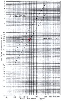
- 4 Row 8 fpi Cooling Coil pressure drop = 0.60 inWg (See Fig. 4; Ref. 4);
- Internal air handler casing pressure drop = 0.10 inWg (assumed: from the RA/mixing box to the SA fan inlet, comprised of internal structural constraints within the air-handler casing) - See Note 3 below at end of article;
- Total “Design” ESP (external static pressure) = 8.50 inWg, where the:
Supply air side ductwork ESP = 4.50 inWg, and...
Return air side ductwork ESP = 4.00 inWg.
- The total design ESP calculation was estimated by the design engineer using quick “rule of thumb” methods as opposed to a detailed “air handler to terminal device” (item to item) computation.
Concerns
Let’s now examine how on the return side the pressure can become problematic and endanger the air-handler casing.
If the original pressure drop calculation on the return side wasn’t accurately calculated (to reflect the layout as designed and intended), but done with quick, “rule of thumb” estimates, and the actual system pressure (when commissioning and air balance is done) turned out to be greater than expected, then the fans would underperform. Less airflow would be the result. To compensate, they’ll have to ramp up the fan’s rpm to deliver the required cfm. This in turn will increase the pressure in the duct system further, as well as increase the fan’s hp (and electrical usage) requirements.
On the other hand, if the ESP was over-estimated, then the fans will overperform. In that case, throttling the airflow to bring it down to “spec” will be needed.
Continuing, let’s say – at the design airflow of 30,000 cfm – the actual TAB measured return air side pressure drop is 4.70 inWg, instead of the estimated 4.00 inWg. This is an 18% jump….not an insignificant increase.
The measured result is just outside the air-handler at the main RA trunk leading into the bottom of the air handler; see Fig. 1 (i.e., the losses at the air handler’s RA damper are not accounted for). This excess dp reading could be because of the “rule of thumb” estimate, that underestimated the losses, as well as the duct system being rerouted in places (extra elbow fittings, etc.) to pass around obstructions and other utilities not expected to be present with the intended design routing, and/or smaller duct sizes (extra transition fittings required and higher dP with smaller ducts) needed to squeeze through tighter spaces.
Return Side dP Analysis
Let’s add the following air-handler internal component pressure losses (dP), starting at the RA opening in the air handler and proceeding towards the supply fan:
- RA damper dP: 0.292 inWg (based on: (Vel/4005)2 x C = (3000/4005)2 x 0.52);
- MERV 11 dirty filter dP: 1.00 inWg (assuming they’ll not swap out filters until it reaches the dirty stage);
- Heating Coil dP: 0.15 inWg;
- Cooling Coil dP: 0.60 inWg;
- Casing dP: 0.10 inWg (frictional losses as air travels from the RA box to the SA fan inlet).
Note: I’ll not include the OA damper losses here in order to simplify the discussion and analysis.
So, total air handler component losses on the return air side = 2.142 inWg. (Let’s round to 2.14.)
Now, add this to the measured RA ductwork ESP of 4.70 and we have 6.84 inWg, negative pressure.
Comparing this to the air handler’s casing pressure limit of -/+ 8 inWg, we see that we have approx. 1.16 inWg of margin. This seems safe enough, but…
What Could Go Wrong?
Aside from the excess duct static pressure situation that was not initially assessed correctly – and can now become a thorn in your side – the following needs to be considered:
- If the air filters are neglected and allowed to reach and pass their dirty rating, filter dP and system dP continues to increase;
- As the filters load up and are left in place they’ll likely start to buckle due to the high differential pressure across their surfaces, and the frames can bend and separate from the filter tracks possibly allowing unfiltered air to bypass the filters, dirtying the coils, fan and ductwork downstream of the air handler. This is not a scenario you want at all;
- Now, if you have two filter racks, a pre-filter and a final filter rack, your problem increases…the dP across each filter bank is cumulatively added together;
- Should the coils go neglected and uncleaned and start to clog up, then your coil dP increases substantially. This is not only a static pressure problem, but also a coil performance concern (i.e., as the coils load up with dirt they don’t transfer heat as needed);
- Also, damper operation is very important. The RA damper can get hung up in time without proper maintenance and not open fully at design airflow. Consequently, you’re looking at a higher loss coefficient that can approach say 3.16 (with blades at 20 degrees away from centerline – refer to Fig. 2), resulting in a loss (i.e., more resistance) across the damper of (3000/4005)2 x 3.16 = 1.77 in Wg, as compared to 0.292 in Wg expected initially - a difference of 1.48 inches of pressure. If stuck in a more closed position, the coefficient C increases dramatically….just look at the Fig. 2 chart to see how C blows up exponentially;
- If the RA damper was neglected, then you can assume the OA damper may have been also. With a stuck OA damper (or dampers) in a more closed position, then you’ll be adding more negative static pressure as well.
However, considering only a stuck RA damper (and not accounting for dirty coils), now you’re at 8.32 inWg of negative pressure on the return side (6.84 + 1.48).
The air handler’s casing panels may have started to deflect inward now. Panel seams and sealing will be affected. Opening the AHU’s access doors will also be more difficult.
Remember, all this extra static pressure now hampers the operation of the SA fan, reducing its ability to move the same amount of air through the system as before. When fans encounter more static pressures than intended, they will ride up on their performance curve and deliver less air (Ref. 2). When airflow is reduced, cooling and heating of the spaces suffers and discomfort can start to be felt by people inside. Your SA contains a percentage of fresh OA; a reduction of this starts to be felt indoors as well.
CONCLUSION
The above situation, although only analytical in nature, reveals the possible pitfalls that may befall the equipment, if not maintained properly, or the system if not properly designed. Of course, these equipment pitfalls are not limited to hospital applications.
Naturally, you, the designer, cannot control a client’s maintenance operations, but it is worthwhile knowing what could go wrong. At the very least you can design the system to minimize system static “design” pressures to increase the safety margins between the system’s design pressure and the pressure the air handler casing can withstand. If this gets to be problematic and you cannot build in more margin, you may need to request stiffer casing panels from the equipment manufacturer if possible, or include a return fan in the return box section.
Further, the facility’s operations personnel and owner need to understand that maintaining the equipment properly will avert more costly situations down the road. You may need to enlighten them on these items in detail to drive home the concerns.
TAB readings taken inside the return/mixed air box, and in the supply discharge air box, while the air handler is at design airflow would be a good data point to keep handy as reference. Also, the same measurements taken with clean filters and coils, as well as dirty filters and coils, will be a useful data point baseline to have. Later, after other renovations to ductwork layouts and schemes have changed, these same measurements should be taken (and compared) to see what margins remain. Reduced margins would signal a need to keep an eye on maintenance more closely, or to take some other corrective actions.
Finally, do not underestimate the value of what appears to be a minor detail, or its ability to cause problems for the equipment, and headaches for both the owner and you, the designer. It can and likely will do so if it is overlooked or dismissed as inconsequential.
Keep in mind that accuracy in engineering is vital. Detailed calculations and attention to all matters, minor and major, need to be considered to ensure the best possible outcomes. Otherwise, much can go wrong, very quickly!
P.S. My mom made it home okay from the hopsital just a few days later.
##########
References
- ASHRAE 2005, Fundamentals: Chapter 35, “Duct Design”;
- ASHRAE 2004, HVAC Systems and Equipment: Chapter 18, “Fans”;
- Camfil 2 inch deep MERV 11 Pleated Panel Filter;
- SMACNA Duct Design Manual, 1981 Edition.
Notes
- The symbols within parentheses represent the amount of negative or positive pressure found in each section of the air-handler;
- The OA damper is adjusted and positioned as a throttling device to limit the OA cfm to that needed while ensuring the fully open RA damper allows passing of full RA design airflow.;
- I recall (during my days dealing with larger well known AHU vendors) that equipment submittals included in the machine’s total pressure calculation, a small allowance for the pressure losses thru the casing, above and beyond the estimated amounts for filters, coils and dampers.
##########
