Engineering A2L Compliance Into Multifamily VRF Systems
Key Highlights
- A2L VRF systems are governed by the smallest room served, not by average or maximum room sizes, affecting overall refrigerant charge limits;
- Design strategies include segmenting circuits by room size, minimizing piping volume, and routing larger circuits to common areas to stay within charge limits;
- Vertical refrigerant risers must be routed through dedicated, ventilated, fire-rated shafts, requiring early design coordination to prevent costly redesigns;
- Detection systems should be placed considering refrigerant vapor density, with trigger thresholds set below flammable limits to ensure safety and compliance;
- Retrofitting existing VRF systems with A2L refrigerants demands careful review of piping layouts and charge distribution to avoid non-compliance and costly modifications.
By TARANG PATEL, CPHC, TRV Mechanical Contractors LLC
A variable refrigerant flow (VRF) system doesn't have one refrigerant charge — it has one charge distributed across every indoor unit sharing that circuit. That distinction, which barely mattered under R-410A, is now the single most consequential variable in designing a compliant A2L VRF system for multifamily high-rise construction.
Today, the general A2L code framework — charge limits scaled to room size, detection and mitigation above threshold, listed equipment and labeled piping — applies the same way to a single-zone mini-split as it does to a 40-unit VRF branch circuit.
But the engineering problem is not the same.
A single-zone system has one indoor unit and one room to evaluate against the charge limit. A VRF system distributes one outdoor unit's total refrigerant charge across a refrigerant circuit that may run through a dozen apartments on multiple floors — and the code doesn't let you average that charge across all of them. In my work directing mechanical engineering for VRF-heavy high-rise residential developments, this has become one of the first calculations on the page, not a compliance check done after the layout is set.
Governing Constraint: The Smallest Room on the Circuit
The core design rule that trips up teams new to A2L VRF work is this: a multi-zone system's applicable charge limit is governed by the smallest occupied space any indoor unit on that circuit serves — not by the average room size, and not by the building's largest space.
If a single refrigerant circuit feeds indoor units in a 90-sq-ft bedroom and a 400-sq-ft great room, the circuit's total allowable charge without triggering detection and mitigation requirements is set by the 90-sq-ft room's limit, applied against the full system charge that could theoretically concentrate there in a worst-case leak scenario.
This single constraint reshapes VRF branch design in multifamily buildings, where bedrooms — the smallest conditioned spaces in a typical unit — are common termination points for indoor fan coils. A layout that groups too many indoor units, or too much total refrigerant, onto one outdoor condenser will frequently exceed the allowable charge for its smallest served room well before it approaches any mechanical capacity limit. The refrigerant-safety constraint, not the cooling load, increasingly determines how many apartments a single VRF condenser can serve.
Design Strategies for Charge Management
Once charge becomes the limiting variable, several design approaches — used in combination more often than alone — bring a VRF layout back into compliance without abandoning the efficiency and footprint advantages of shared condensers:
-
Segmenting branch circuits by room size. Rather than one large condenser serving an entire floor or riser, split the system into smaller circuits sized to the charge limit of their smallest served room, using multiple smaller outdoor units instead of one large one;
-
Minimizing total refrigerant piping length and volume. Shorter branch runs and tighter routing reduce total system charge directly, since refrigerant charge scales with pipe volume as well as indoor unit capacity;
-
Reserving larger shared circuits for larger rooms and common areas. Living rooms, amenity spaces, and corridors tolerate higher charge limits than bedrooms; routing the largest-capacity branches to these spaces, while giving small bedrooms their own smaller circuit or a non-VRF terminal unit, can resolve a charge conflict without a full redesign;
-
Evaluating heat-recovery versus heat-pump-only architecture early. Heat-recovery systems add branch selector boxes and additional refrigerant piping compared to a heat-pump-only refnet layout, which increases total system charge for the same number of served units — a real trade-off against the comfort and mode-flexibility benefits heat recovery otherwise offers. But this needs to be evaluated against charge-limit compliance specifically, not just first cost.
Shaft and Riser Design for Multi-Floor Refrigerant Runs
High-rise VRF systems commonly run refrigerant piping vertically through multiple floors to reach indoor units on different levels from a single rooftop or mechanical-room condenser. Several jurisdictions now require that vertical refrigerant piping penetrating multiple floors be routed through a dedicated, ventilated, fire-rated shaft rather than a standard wall chase. This requirement has direct implications for architectural coordination, since it affects floor plan layout and structural penetrations on every level the riser passes through.
This needs to be resolved during schematic design, not construction documents. A shaft requirement discovered after architectural floor plans are set is a significantly more expensive problem to solve than one identified when unit layouts are still flexible.
On any high-rise VRF project, I now treat shaft routing and ventilation requirements for A2L piping as a coordination item on the earliest set of drawings shared with the architectural and structural teams, precisely because it has design consequences well beyond the mechanical scope.
Detection Design: Placement, Trigger Thresholds, and Interlocks
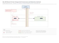
Where a VRF circuit's charge exceeds the applicable limit for its smallest served space, the code requires a refrigerant detection and mitigation system, and the engineering of that system deserves the same rigor as the refrigerant circuit itself. Key considerations:
-
Trigger threshold. Detection systems are generally required to activate mechanical ventilation at 25 percent of the refrigerant's lower flammable limit (LFL) — well below the concentration at which ignition risk becomes real, giving the mitigation sequence margin to operate before a hazardous condition develops;
-
Sensor placement. Detectors need to be located where refrigerant concentration would be highest in a leak scenario, which depends on the specific refrigerant's vapor density relative to air — most A2L refrigerants used in comfort cooling are heavier than air and tend to accumulate near floor level, which should directly inform sensor mounting height and location relative to the indoor unit and likely leak points;
-
Interlock sequence. A properly engineered mitigation sequence ties the refrigerant detector to automatic activation of mechanical exhaust ventilation and, typically, a compressor shutoff or refrigerant isolation valve — engineered as a single coordinated safety sequence rather than as independent devices that happen to share a room;
-
Continuous versus triggered ventilation. Code officials generally accept either continuously operating mechanical ventilation sized for dilution, or ventilation triggered by the detector — a decision with real energy-cost and equipment-sizing implications that should be evaluated project by project rather than defaulted to one approach.
The Retrofit Problem in Existing VRF Buildings
Multifamily buildings with existing R-410A VRF systems face a version of the retrofit trap that's more complex than a single-zone replacement. Because the existing branch circuit architecture, riser routing, and room-by-room charge distribution were all engineered under A1 refrigerant assumptions, a straightforward like-for-like replacement of aging VRF equipment with an equivalent A2L system can put the existing piping layout out of compliance — even where the outdoor equipment footprint and capacity are unchanged.
Any capital-planning conversation about VRF equipment replacement in an existing high-rise now needs a refrigerant-charge compliance review as an early scope item, not an assumption that the existing riser and branch configuration can simply be reused.
Conclusion
A2L compliance in multifamily VRF is not a matter of specifying a listed condenser and moving on. The room-by-room charge constraint reshapes how branch circuits get segmented, how many apartments a single outdoor unit can serve, how refrigerant risers get routed through a building section, and how detection systems get engineered when charge limits are exceeded.
None of this is exotic engineering — it's a well-documented, code-driven design constraint — but it has to be worked through at the layout stage, in coordination with architectural and structural teams, rather than discovered during commissioning. Buildings designed with this sequence in mind will move through permitting and inspection considerably faster than those that treat refrigerant safety as a product-selection footnote.
####
The author is an HVAC mechanical engineer with TRV Mechanical Contractors LLC in Kenilworth, NJ. Contact him at [email protected].